
It's about the time now that the oldest of the UVC-G4-Doorbells are running out of warranty. I've had two of them so far fail and one was just within warranty and one just fell outside.
The failure mode is a momentary loss of power when someone rings the bell. The Doorbell has an unusual (for network equipment) power arrangement where it is fed by 16-24VAC. This is to maintain backwards compatibility with very old mechanical doorbells.
Ubiquiti has a clever workaround whereby the power needs to be cut momentarily to the electronics to allow the mechanical doorbell to ring. This is done via an onboard battery arrangement. I suspect this wears out over time. Given I was out of warranty I wanted to see if it was a quick fix to repair.

(Click on any of these images to enlarge)
Opening the doorbell is quite straightforward. There are 6 Torx T5 screws around the outside and two Phillips screws where the power comes in. The two Torx screws nerest the UniFi logo have little seals on them so it's pretty easy to remember which one goes back where.
Once you remove those screws you can carefully flip the case open, just keep in mind that there is a ribbon cable and a connector (labelled BAT1) that you want to avoid breaking.

You can leave the ribbon cable alone, but the BAT1 needs to be carefully lifted up (pry vertically not horizontally) and it will disconnect.
You will then find two black Torx screws that need to be removed. one is on the bottom right of this image and one is near the square IC. They are conveniently marked SCREW. On mine there is a blank additional place marked SCREW (next to MH1) that didn't have a screw in it. You do not need to remove the large flat Phillips screws (they hold the camera on the other side). You also do not need to disconnect the white connector. You do need to remove the ribbon cable connected to J33 (it just pulls out) and also the ribbon cable attached to J34 which also pulls out. Lastly you want to remove the red/black wire connected to CON1 , this also just lifts up. You can now get to the next level.

There are two types of power sources here. There is a double-battery arrangement which you can just disconnect at the top and also a capacitor at the bottom left which is connected to BAT2.
The capacitor is a 50V 220μF radial electrolytic made by AiSHi. It was marked 1844JPET which isn't a part number, but it seems from the AiSHi web site that it's an RJ series part number ERJ1HM221G1BOT. Size is 10mm diameter, 12.5mm height. When I did a test with my DMM it tested out to 202μF which is within the ±20% spec on the AiSHi web site.
Next was to look at the battery which is made up of two connected modules.
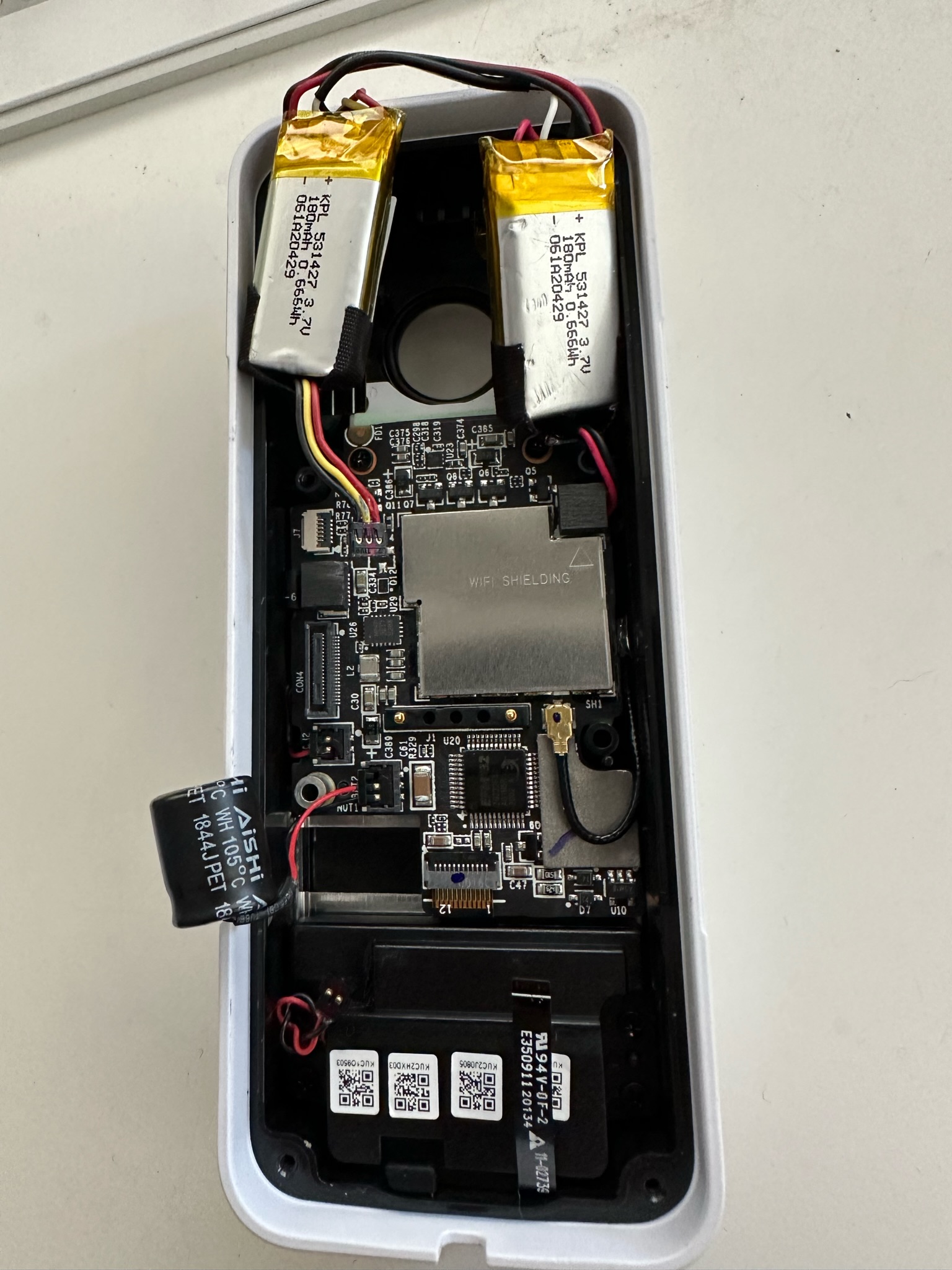
Here is the photo from front/back. They are two 3.7V 180mAh LiPo modules wired up in parallel. They actually looked to be on OK shape, they were not obviously swollen and my DMM measured 4.01V. This test was not done under load though so it's not certain that the batteries are still actually good.
Then I ran out of time... so next step would be to see how this performs under load, but I haven't seen any other teardown pics online so I thought putting these here would get the ball rolling for someone else to do a bit more investigation if they have the same problem.
In the end, I simply bought a new one and it fired up and works perfectly (which shows that the power supply is not the issue - something I tested right up front before doing all this).

Good afternoon!
ReplyDeleteThank you so much for your report!!!)))
What do you think you can put one battery on 360-400 mA and place it in the room lengthening the wires. To exclude the operation of the battery at low temperatures. Thinking that this way you can solve the problem of rebooting the intercom at low temperatures.
Thanks for posting this teardown. I just wanted to share my experience. I was experiencing the power loss as well, and the battery voltage also checked out fine. I noticed that one of the pogo pins that connects the terminals to the board was bound up and stuck. The back of the terminal where it makes contact also had some evidence of arcing. I couldn't unstick it so I soldered wire directly to the pogo pins and to the back of the terminals. The doorbell has been completely stable since then. I don't know why they chose to use pogo pins for this application, it doesn't really make sense.
ReplyDeleteHad the same issue and soldering the two pins to the connections worked like a charm!
DeleteHi, do you have some link for replacement batteries? Did you try?
ReplyDeleteI ended up just getting a new one instead of replacing the batteries. If anyone else knows a good source, leave a comment.
Delete