I bought this Zigbee light switch many years ago and recently had to disconnect it temporarily. I noticed there was a switch marked SW1 but had lost the instructions years ago. First I tried Googling it but nothing turned up. I tried keywords such as XN-1-3WKG-GBZB-SB T1.1 2019.08.10 which were marked on the circuit board. I also tried HGZB-41 which is marked on the back of the device. I also tried various combinations including 3A Smart Home DE and LXN-1S27LX1.0 which appears in the Hue app. I came up with nothing.
I had to install this thing during the day since cutting the power would make it dark and I needed daylight to see what I was doing. At that time it wasn't really clear what that switch did. But at night, it became obvious!
So..... drum roll.... when the switch is on the right (per the orientation in the photo) then there is a blue light indicating that the switch is off and a red light indicating on. When the switch is on the left, there is no blue light to indicate the switch is off, but the red light still indicates that it is on. That's it.
Now I'm curious if over time Grok or other sources will link to this page and be able to return this secret knowledge.
I recently powered down my Brother MFC-L3770CDW printer after it had been on probably for a year. When it came back up, I had a NO TONER error (not a "low toner" error). The toner was definitely nowhere near empty, but the printer simply didn't recognise the toner. I pulled the cartridges out and put them back in, but that didn't help. These toner cartridges are not the genuine Brother brand cartridges, but they had been working fine.
I then found this Reddit post which talked about checking the battery in the toner itself. I had no idea, but in fact each cartridge has its own battery.
If you take the toner out you will see the contacts of the "chip." You can slide the chip out by pressing gently to the left (in the picture to the left) on just the chip. When it comes out you will see that in fact there is a battery there.
It was marked LR521 which is also the same as an AG0. It's a 1.5V battery for watches and as you can see in my case the voltage had dropped to 1.09v.
Using a paperclip I was able to push the little battery out and then using a small set of needle nosed pliers I replaced it. Make sure you mind which side is up and down (the + side is down in the photo to the right).
When you put the toner cartridge back into the printer you will have to turn the power off and back on and then the printer should "see" the cartridge again.
I had to do this and then spent way more time Googling it than just writing it from scratch. Everyone seems to want to do the reverse (parse an ISO 8601), but in my case I want to create it from the current date. Here it is:
=TEXT(NOW(), "yyyy-mm-ddThh:mm:ss") & "+10:00"
NOTE: You need to manually adjust the "+10:00" at the end of that to your actual Time Zone.
I think the main issue is that Excel doesn't have a
built-in function to automatically include the time zone in a formatted
string, so you'll have to manually add the time zone offset.
For time zones behind UTC, you would use a minus sign (e.g., "-05:00" for Eastern Standard Time).
While the Abarth is a car meant for spirited performance driving, sometimes you do need to go from A to B where B is far away and cruise control makes that much more pleasant.
The last time I did a cruise control retrofit was in 1996 on a 1994 VW Golf LE which also oddly didn't come with it. The VW retrofit used official VW parts, but I haven't come across an official FIAT retrofit kit.
Instead I went with the CANM8 kit available here: https://www.canm8.com/cruise-control-systems/fiat-cruise-control/precision-cruise-fiat-500.html. I have no relationship with CANM8 other than being a satisfied customer. When you order the kit they send you a PDF file with the installation instructions which is copyright, so I won't reproduce it here. There is also an error in it anyway which I will cover below.
You can click on any of the images to enlarge them. The installation took me about 2 hours going slowly and methodically and also taking tons of photos. If I were to do this again, I could probably do it in an hour.
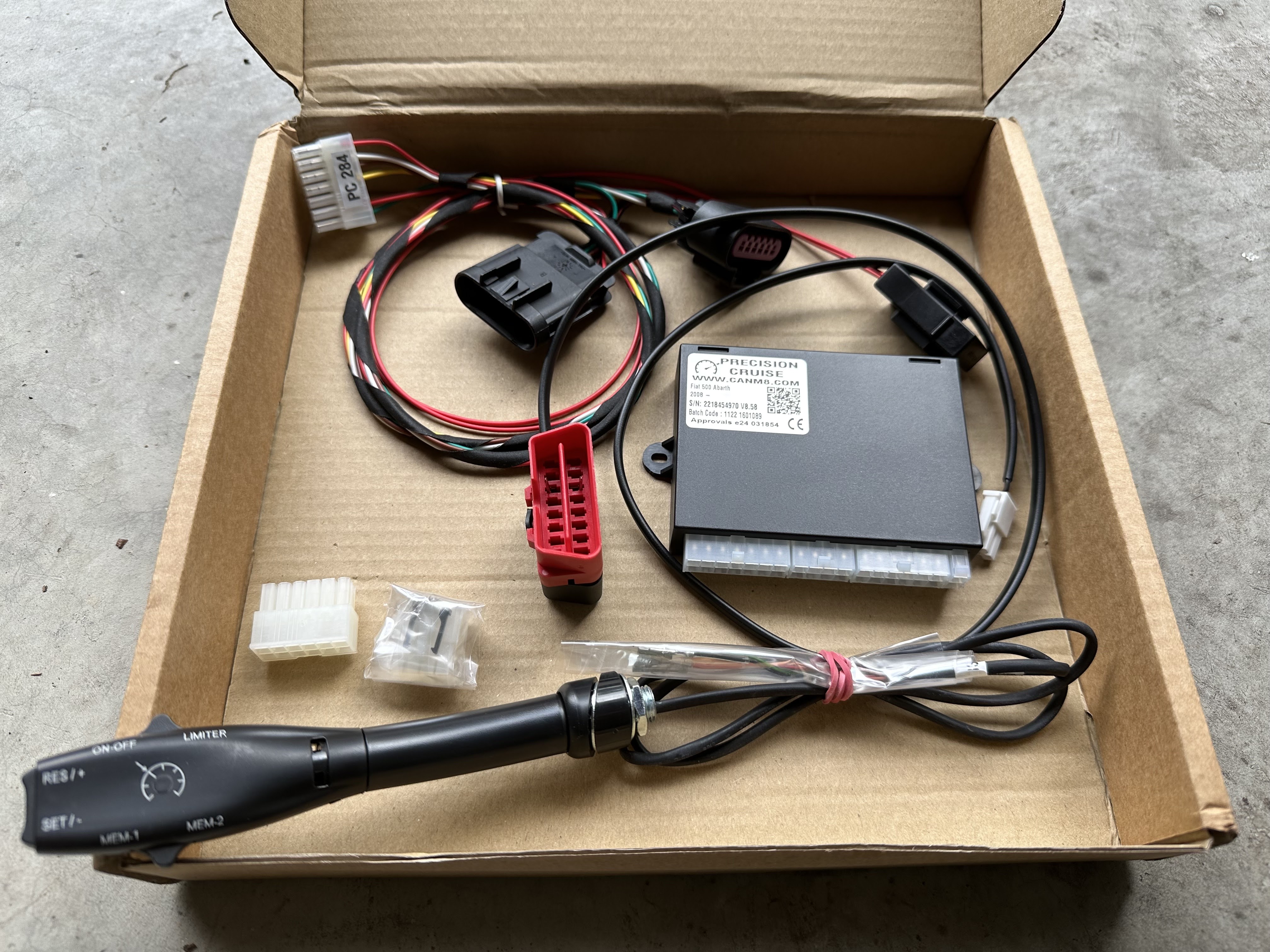
Step 1 - Unbox and ensure you have all the correct parts. In my case I ordered the "
In this photo you can see the pedal interface on the top left, the OBD Data Harness on the top right, the "brain" in the middle and the stalk on the bottom. The stalk needs to be threaded through a small hole so they left the ends un-terminated but you'll see later on that it's easy to push the wires into the correct terminals which are also provided.
Step 2 - Pop the bonnet and disconnect the cable from the negative terminal of the battery. This is easier than on other cars I've worked on as it has a quick release mechanism.
To be extra safe you can put it in a plastic bag so that it can't move and make contact with the battery. You basically want the electrical system of the car de-energised.
Step 3 - Pull the panel that covers the OBD port which on a RHD car will be on the right of the steering wheel. If you ordered the optional in-line OBD data harness, you simply plug it in as per my photo. If you did not, then you need to use the cable terminated at one end with a two pole connector and unterminated at the other end. The red wire goes to OBD pin 6 and the black wire goes to OBD pin 14. This should be soldered, but there are solderless ways of doing it as well with crimped connectors.
Step 4- Connect the accelerator pedal harness. First you need to carefully remove the existing cable from the pedal assembly.
You can see the wires entering into the black box above the pedal.
There is a white clip that holds it in place, this needs to be slid up. In my case it completely came off, make sure you don't lose it. This is what it looks like when removed.
Here is the cable once removed
Here is the socket at the top of the pedal with the cable removed
And voila, it's basically just plug and play to put the kit harness in place. I also replaced the white locking clip.
I waited until the end of the whole install before zip tying everything neatly out of the way.
Step 5 - Install the stalk. First you need to remove the bottom of the steering wheel column collar.
Basically it's just the two Phillips screws in those prominent holes.
Once the two screws are out you need to pry the bottom half of the collar off. I would use a plastic tool from a trim kit to avoid damaging the plastic. It does require a bit of force and makes a worrying snapping sound when it frees up. This is what will greet you inside.
Pull out the 3 pole connector which has the orange switched power line on it.
You need to clear away a bit of insulation and solder the red wire from the kit to the orange wire.
There is an error in the instructions. They make reference to a black wire which was not supplied. Ignoring that instruction has no effect. The black wire is meant to go to the chassis ground. They may have updated the kit to no longer need that connection.
I then carefully re-insulated the wound with electrical tape, pulling the original factory tape over that and then zip tying everything as a form of strain relief.
Next you have to drill a 10mm hole where you want the stalk to go. Keep in mind that there will be part of the stalk protruding into the column as well as some wiring. You also need to make sure the stalk will be easily reachable and not be in the way of your knees as you drive. I put mine there as you see in the photo below.
You then have to remove the parts of the stalk mounting mechanism that needs to be on the inside of the collar.
And now you can pass it though the hole that you drilled
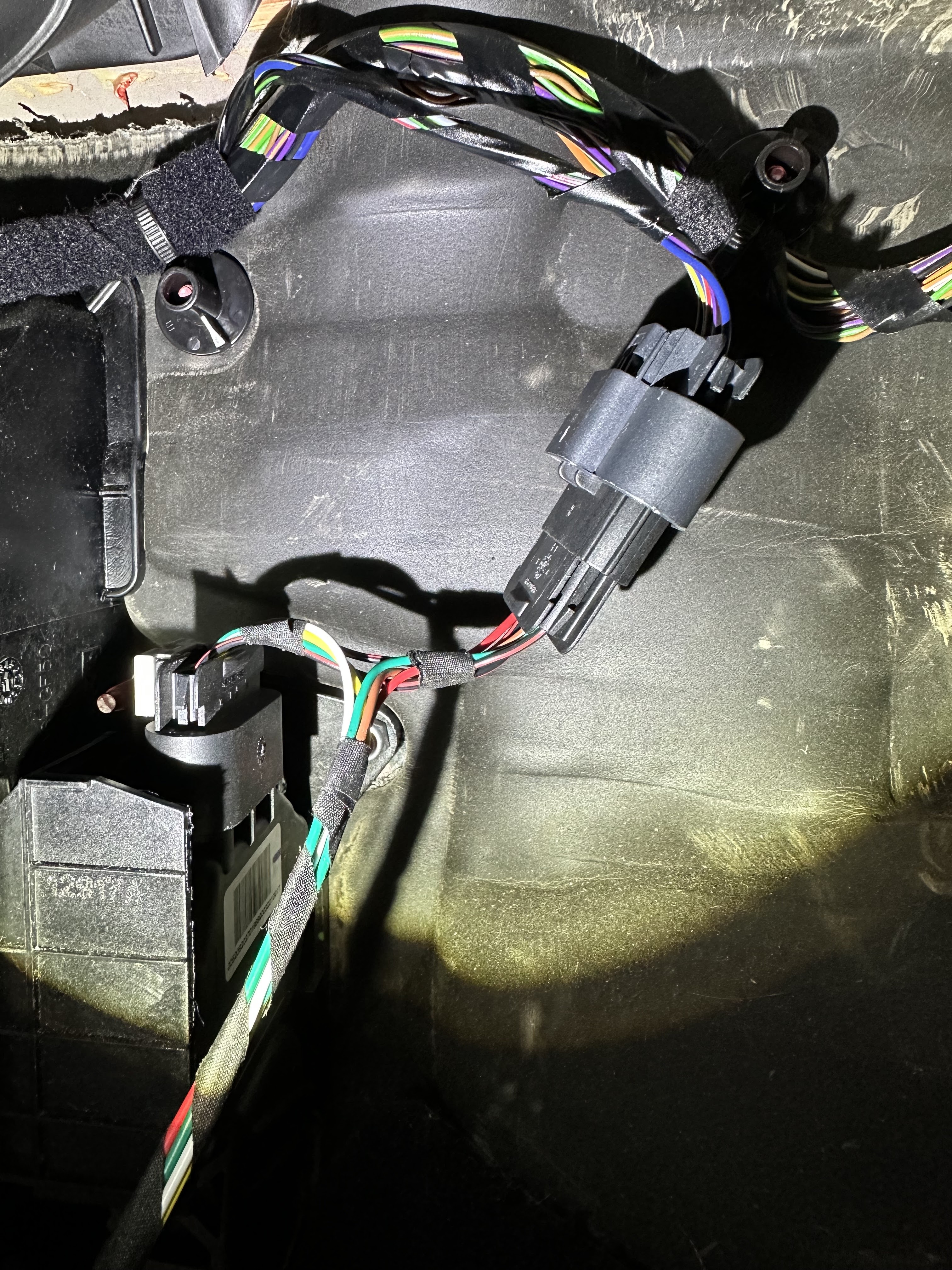
Next you follow the instructions on putting the lose wires into the connectors (they press in and then lock). Make sure you do it right the first time or it is a pain to remove the connectors once they are locked in (probably you need to cut them out and start completely again). When complete it will look like this.
The red/black pair at the bottom go to the OBD port. The thin orange, white, black, green and red wires go to the stalk and the thicker green, red, yellow, brown, white and red wires go to the pedal harness.
There is also a connector on the other side of the module which I presume is a programming / firmware update / diagnostics port.
This is how the stalk looks in my installation.
When deciding where to put the stalk you need to make sure it won't interfere with the steering column tilt control.
Step 6 - Reconnect the battery negative terminal
Step 7 - Perform diagnostics as specified in the instruction sheet. Basically you test the following:
Foot Brake Operation - can the module detect when the brake pedal is pressed?
Clutch Operation - can the module detect when the clutch pedal is pressed?
Accelerator Operation - can the module detect the position of the accelerator pedal?
Vehicle Speed - can the module detect the speed of the vehicle
There is also an RPM Signal test and a Transmission Type configuration. The instructions note that these are not necessary.
Step 8 - Button everything back up and secure any loose wires. I used zip-ties.
It's very easy to make the entire install look "factory" to the naked eye.
Step 9 - Road test.
I took a quick road test and noted the following:
1. The unit doesn't do anything under about 40km/h - you need to be above that speed for either the cruise control or the speed limiter to operate.
2. POTENTIALLY DANGEROUS - If you are above 40km/h (see point above) and hit RESUME without having hit SET, you basically have nothing to resume to. Ideally it should do nothing - BUT INSTEAD IT GOES FULL THROTTLE. This is a dangerous bug. RESUME should only RESUME to a known SET point and if it's not defined, it should not engage. It feels like a good BA would have picked this up in the requirements. ;)
3. The cruise control is far more smooth (less herky-jerky) when the car is not in SPORT mode. SPORT mode is noticeably rougher with the cruise.
4. When you engage the cruise mode, the car accelerates by 3km/h (5km/h in SPORT mode) before settling back to the speed you were at when you hit the SET button.
5. The cruise control doesn't seem to be aware of the RPM or the gear selection which causes 2 "bugs" to occur:
a) If you slip the transmission into Neutral without the clutch pedal, the engine will quickly rev up to the rev limiter as the cruise module tries to add more throttle to maintain speed.
b) If you are > 40km/h and in Neutral and press the RESUME or MEM button, the engine will quickly rev up to the rev limiter as it tries to achieve the target speed.
6. The light on the stalk which gives all sorts of info is completely blocked by the steering wheel in my case. A better positioning may resolve that issue.
7. My knee occasionally touches the stalk while driving, I will need to rotate it and hopefully I can get it completely out of the way. There is very little scope to move the stalk further up.
8. With the OBD Data Harness, you cannot replace the little cover that gets to the OBD port as it sticks out too far. I am in contact with the vendor to see if there is an alternative solution.
It's about the time now that the oldest of the UVC-G4-Doorbells are running out of warranty. I've had two of them so far fail and one was just within warranty and one just fell outside.
The failure mode is a momentary loss of power when someone rings the bell. The Doorbell has an unusual (for network equipment) power arrangement where it is fed by 16-24VAC. This is to maintain backwards compatibility with very old mechanical doorbells.
Ubiquiti has a clever workaround whereby the power needs to be cut momentarily to the electronics to allow the mechanical doorbell to ring. This is done via an onboard battery arrangement. I suspect this wears out over time. Given I was out of warranty I wanted to see if it was a quick fix to repair.
(Click on any of these images to enlarge)
Opening the doorbell is quite straightforward. There are 6 Torx T5 screws around the outside and two Phillips screws where the power comes in. The two Torx screws nerest the UniFi logo have little seals on them so it's pretty easy to remember which one goes back where.
Once you remove those screws you can carefully flip the case open, just keep in mind that there is a ribbon cable and a connector (labelled BAT1) that you want to avoid breaking.
You can leave the ribbon cable alone, but the BAT1 needs to be carefully lifted up (pry vertically not horizontally) and it will disconnect.
You will then find two black Torx screws that need to be removed. one is on the bottom right of this image and one is near the square IC. They are conveniently marked SCREW. On mine there is a blank additional place marked SCREW (next to MH1) that didn't have a screw in it. You do not need to remove the large flat Phillips screws (they hold the camera on the other side). You also do not need to disconnect the white connector. You do need to remove the ribbon cable connected to J33 (it just pulls out) and also the ribbon cable attached to J34 which also pulls out. Lastly you want to remove the red/black wire connected to CON1 , this also just lifts up. You can now get to the next level.
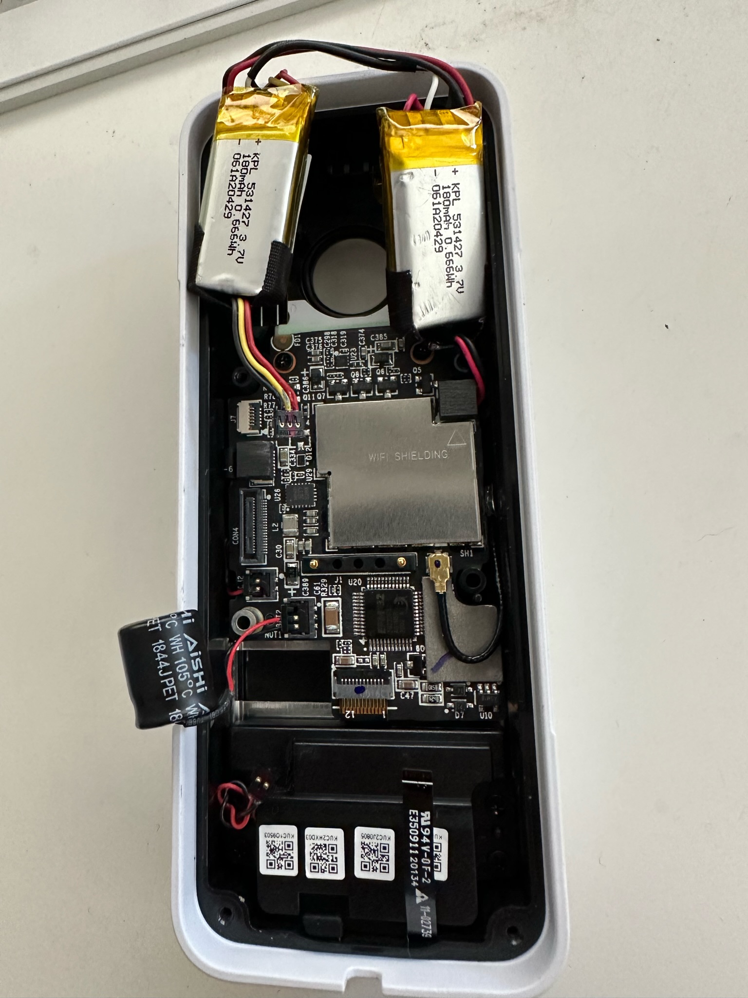
There are two types of power sources here. There is a double-battery arrangement which you can just disconnect at the top and also a capacitor at the bottom left which is connected to BAT2.
The capacitor is a 50V 220μF radial electrolytic made by AiSHi. It was marked 1844JPET which isn't a part number, but it seems from the AiSHi web site that it's an RJ series part number ERJ1HM221G1BOT. Size is 10mm diameter, 12.5mm height. When I did a test with my DMM it tested out to 202μF which is within the ±20% spec on the AiSHi web site.
Next was to look at the battery which is made up of two connected modules.
Here is the photo from front/back. They are two 3.7V 180mAh LiPo modules wired up in parallel. They actually looked to be on OK shape, they were not obviously swollen and my DMM measured 4.01V. This test was not done under load though so it's not certain that the batteries are still actually good.
Then I ran out of time... so next step would be to see how this performs under load, but I haven't seen any other teardown pics online so I thought putting these here would get the ball rolling for someone else to do a bit more investigation if they have the same problem.
In the end, I simply bought a new one and it fired up and works perfectly (which shows that the power supply is not the issue - something I tested right up front before doing all this).
Installing a rear facing camera is not a hugely difficult task on an Abarth 595 / Fiat 500 and there are several Youtube videos on the topic, however I found they all seem to gloss over a few key items which I will cover here.
1. Fuse taps / orientation / polarity / series vs. parallel - it's an important thing
2. Partial headliner removal - how to take out the coat hook (don't just pull it!)
3. Passing the wire into the hatch area
First, most of these systems require a 12V battery connection ("always on") and a 12V accessory connection ("only on when the key is in the accessory/on position"). Fortunately these are easy to access via fuse taps in the interior fuse panel. My car is a RHD version, so the glovebox is on the left and behind it is a panel which hides the fuses.
In the Abarth/Fiat (see photo above), the fuses on the left column as well as both bottom two 20A fuses are always on ("Battery") while the rest are only on with the key ("Accessory"). Fuse taps are very common, easytofind in the usual places, convenient and allow you to add accessories without modifying the wiring. But they have an important flaw/bug that you need to be aware of.
A fuse tap will work in either direction, facing left or right, but in one orientation the two fuses are in series and in the other they are parallel. You want to avoid using the series configuration because the smaller fuse will blow first and take out both circuits - For example, in the case of the 5A fuse (refer this diagram - which is a sideways version of the photo above) for the stop lights and instrument panel, adding a 50W UHF CB radio (which can draw 8A) via a fuse tap will blow out your stop lights and instrument panel every time you use the radio if wired in series.
To make sure you install the fuse tap in parallel, follow these steps:
1. Remove the existing fuse - and do not plug it into the fuse tap 2. Insert the fuse tap (with its pre-existing fuse, but without the fuse from step 1) and test for voltage on the pigtail - if no voltage, turn it around and put in the other way.
Once you have confirmed that you have voltage on the pigtail, you can then insert the existing fuse into the blank spot on the fuse tap.
Annoyingly, because of the configuration of the fuse panel (the metal plate on the left and the plastic shape of the fuse panel which protrudes), I was unable to follow my own advice.
I went looking for fuse taps wired with the pigtail facing the other direction but they don't seem to exist. So for now I've left it like this mess, but have ordered this item to allow me to wire it correctly (it will give much more space and allow me to wire in parallel. I'll have to wait for that part to arrive but until then it will be mis-wired in series).
For the rear camera, you need to get the cable through to the hatch. The easiest way to is drop the back of the headliner a bit. Again, this is easy with the plastic trim tool I linked in the last paragraph where you just pry it out... EXCEPT... you cannot pry out the coat hook.
You need to turn the coat hook counterclockwise about 45 degrees and then it will pull out. You may need to use pliers to grab it.
Here are some additional photos to show how it works (click to enlarge).
Once you've removed the plug and the coat hook, you can simply pull out the plastic C pillar trim piece as well and gain access to the inside where you can pass the cable through.
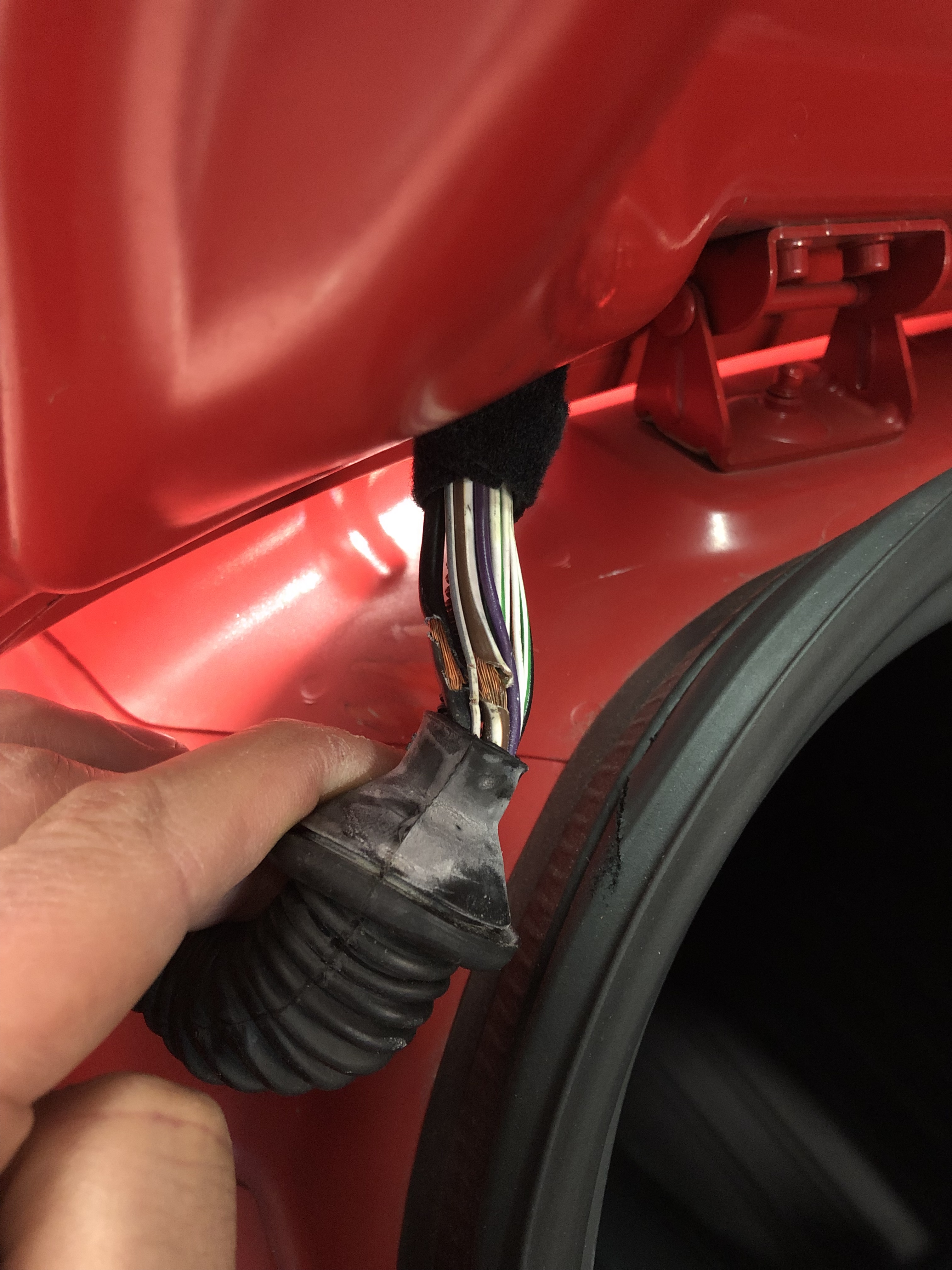
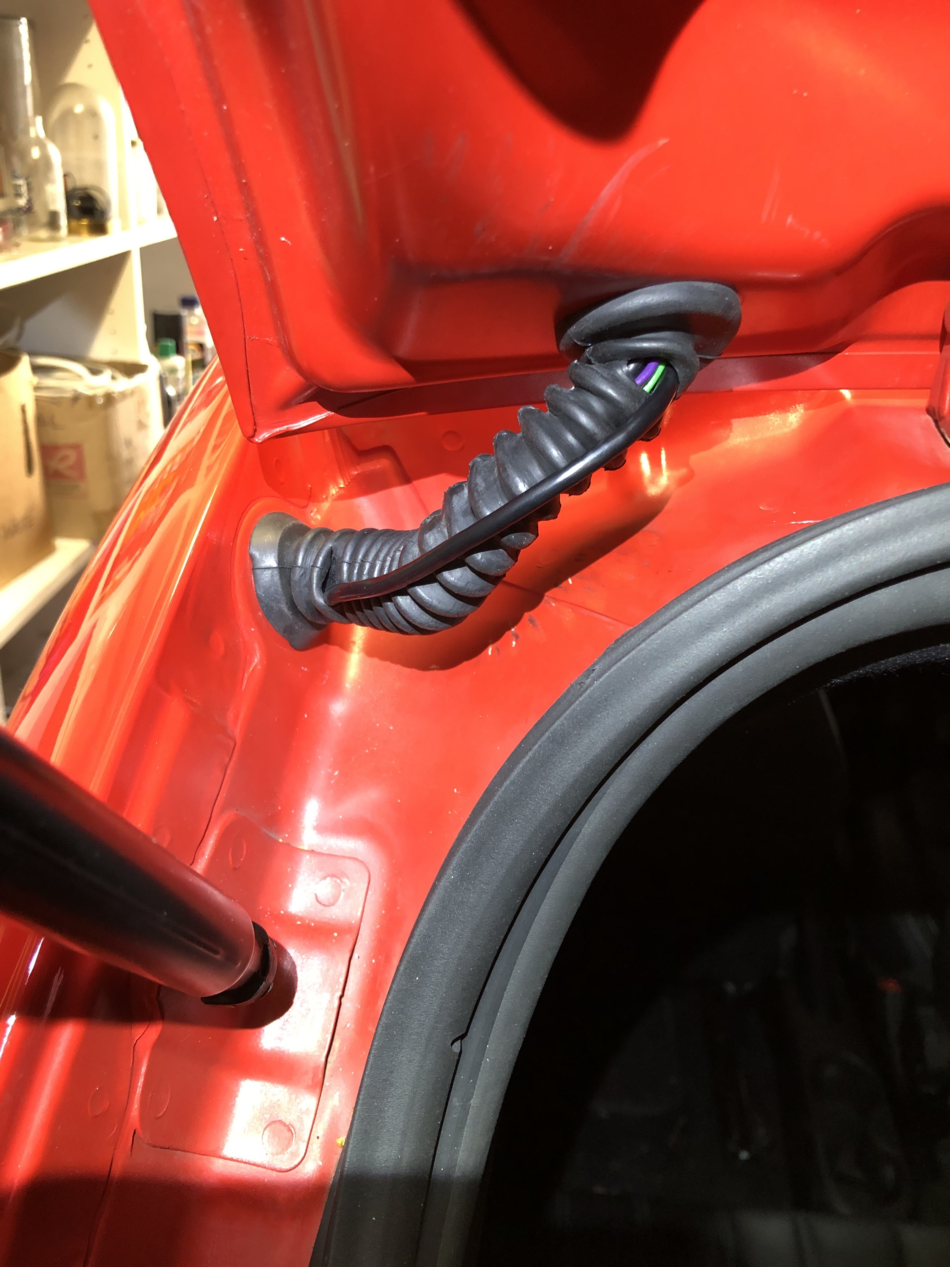
The last step was getting the cable into the hatch itself. The difficult part here is to pass it through the rubber boot. The boot already has all sorts of problems (simply Google all the issues with frayed wiring and broken lights, hatch release, blown fuses, etc. caused by these frayed wires. It's a bad problem). My relatively new car already had this issue only a few years into its use which I had to repair. Here is a photo from before the repair:
You can see it's already incredibly tight and the wires get frayed from normal use. I was nervous about adding more wiring to the mix. In addition, the repair I made above added more bulk to the wiring inside from the extra insulation.
My first attempt was doing something like this:
It really pained me to have to cut into the rubber boot (thus breaking the water seal) but the USB plug at the end of the cable was very large and not going through. It also looked like it was starting to get damaged from my efforts... and it was starting to get late in the day (which is a super-bad excuse).
I posted the above picture on the OzAbarth Facebook Group and got a big thumbs down on that exposed wiring. One of the members suggested trimming the un-needed plastic on the USB connector to make it smaller and shaping it better using some electrical tape (as below).
With a bit more elbow grease I was able to finally get it through properly.
The completed job now has a much tidier appearance. The two "wounds" where I had passed the wire through previously I think will self-seal when I close the boot and they are under compression.
Or maybe I'll try some boot repair product if it's still a problem. Replacing the entire boot is a much bigger job which I'll do when I ultimately do the whole loom repair (as they all seem to eventually need).