The last time I did a cruise control retrofit was in 1996 on a 1994 VW Golf LE which also oddly didn't come with it. The VW retrofit used official VW parts, but I haven't come across an official FIAT retrofit kit.
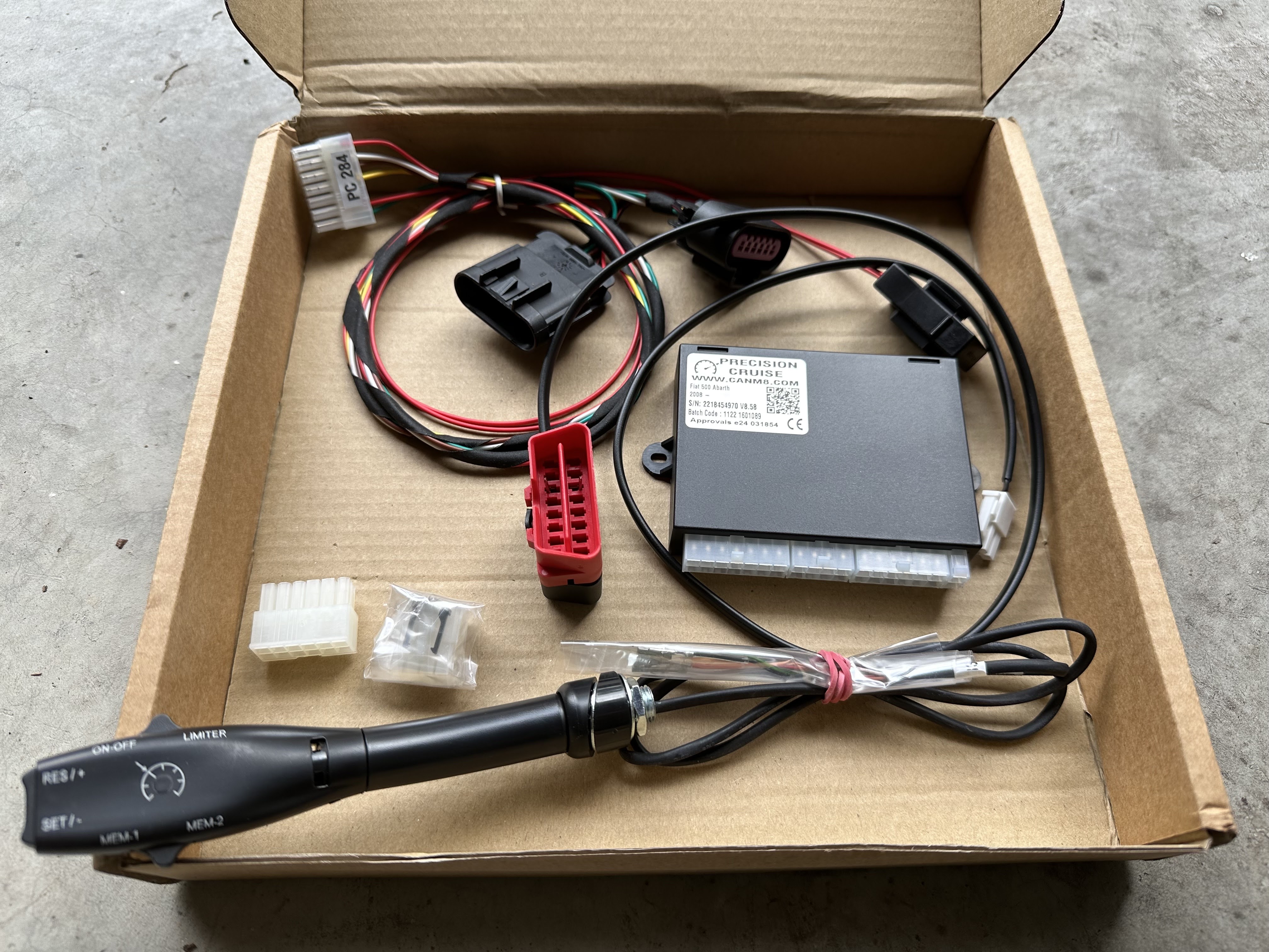
Instead I went with the CANM8 kit available here: https://www.canm8.com/cruise-control-systems/fiat-cruise-control/precision-cruise-fiat-500.html. I have no relationship with CANM8 other than being a satisfied customer. When you order the kit they send you a PDF file with the installation instructions which is copyright, so I won't reproduce it here. There is also an error in it anyway which I will cover below.
You can click on any of the images to enlarge them. The installation took me about 2 hours going slowly and methodically and also taking tons of photos. If I were to do this again, I could probably do it in an hour.

In this photo you can see the pedal interface on the top left, the OBD Data Harness on the top right, the "brain" in the middle and the stalk on the bottom. The stalk needs to be threaded through a small hole so they left the ends un-terminated but you'll see later on that it's easy to push the wires into the correct terminals which are also provided.

To be extra safe you can put it in a plastic bag so that it can't move and make contact with the battery. You basically want the electrical system of the car de-energised.

Step 4- Connect the accelerator pedal harness. First you need to carefully remove the existing cable from the pedal assembly.


There is a white clip that holds it in place, this needs to be slid up. In my case it completely came off, make sure you don't lose it. This is what it looks like when removed.

Here is the cable once removed


And voila, it's basically just plug and play to put the kit harness in place. I also replaced the white locking clip.
I waited until the end of the whole install before zip tying everything neatly out of the way.
Step 5 - Install the stalk. First you need to remove the bottom of the steering wheel column collar.

Basically it's just the two Phillips screws in those prominent holes.

Once the two screws are out you need to pry the bottom half of the collar off. I would use a plastic tool from a trim kit to avoid damaging the plastic. It does require a bit of force and makes a worrying snapping sound when it frees up. This is what will greet you inside.

Pull out the 3 pole connector which has the orange switched power line on it.

You need to clear away a bit of insulation and solder the red wire from the kit to the orange wire.

I then carefully re-insulated the wound with electrical tape, pulling the original factory tape over that and then zip tying everything as a form of strain relief.

Next you have to drill a 10mm hole where you want the stalk to go. Keep in mind that there will be part of the stalk protruding into the column as well as some wiring. You also need to make sure the stalk will be easily reachable and not be in the way of your knees as you drive. I put mine there as you see in the photo below.

You then have to remove the parts of the stalk mounting mechanism that needs to be on the inside of the collar.

And now you can pass it though the hole that you drilled


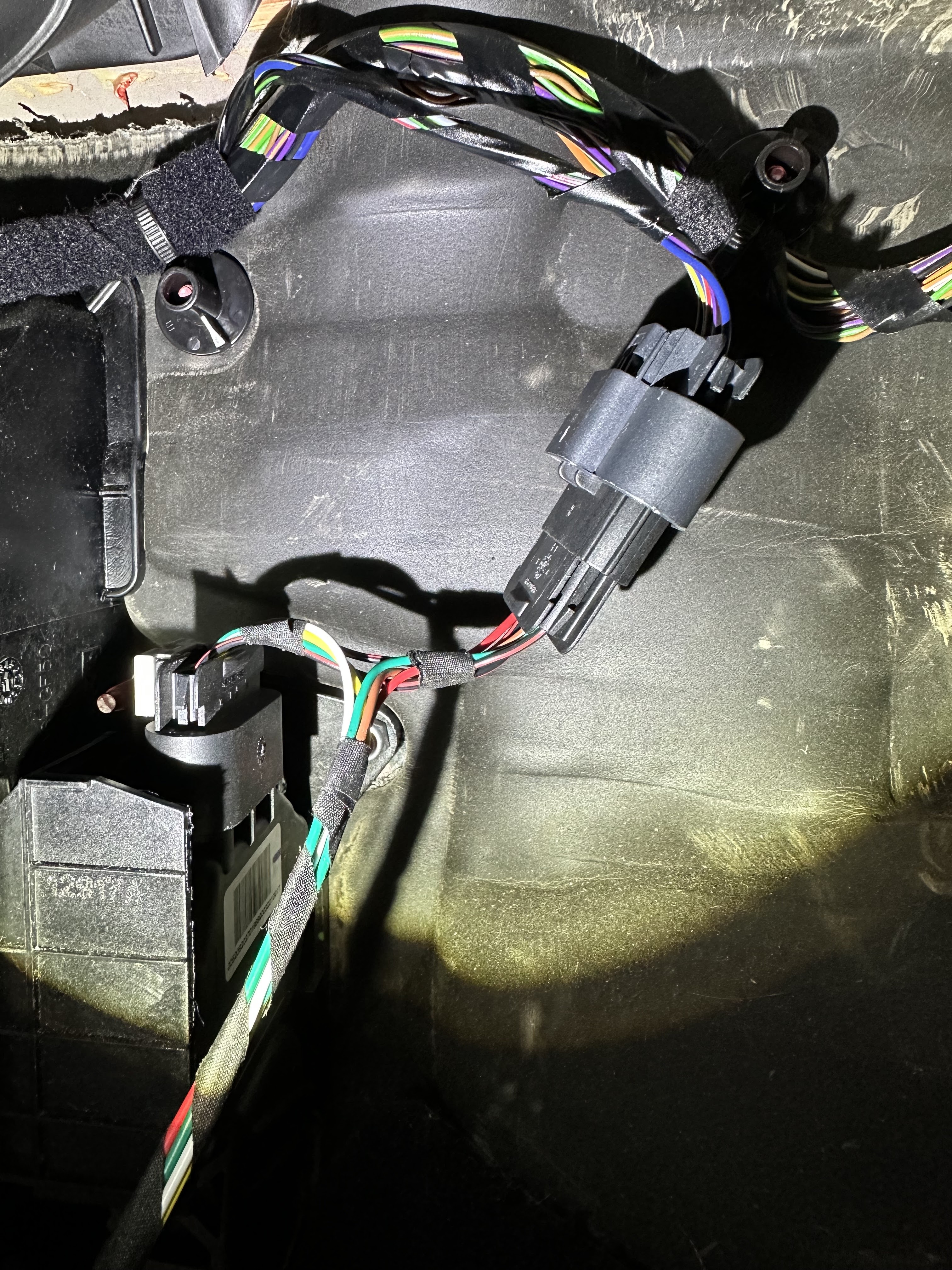
Next you follow the instructions on putting the lose wires into the connectors (they press in and then lock). Make sure you do it right the first time or it is a pain to remove the connectors once they are locked in (probably you need to cut them out and start completely again). When complete it will look like this.

The red/black pair at the bottom go to the OBD port. The thin orange, white, black, green and red wires go to the stalk and the thicker green, red, yellow, brown, white and red wires go to the pedal harness.
There is also a connector on the other side of the module which I presume is a programming / firmware update / diagnostics port.

This is how the stalk looks in my installation.


When deciding where to put the stalk you need to make sure it won't interfere with the steering column tilt control.
Step 6 - Reconnect the battery negative terminal
Step 7 - Perform diagnostics as specified in the instruction sheet. Basically you test the following:
- Foot Brake Operation - can the module detect when the brake pedal is pressed?
- Clutch Operation - can the module detect when the clutch pedal is pressed?
- Accelerator Operation - can the module detect the position of the accelerator pedal?
- Vehicle Speed - can the module detect the speed of the vehicle
There is also an RPM Signal test and a Transmission Type configuration. The instructions note that these are not necessary.
Step 8 - Button everything back up and secure any loose wires. I used zip-ties.
It's very easy to make the entire install look "factory" to the naked eye.
Step 9 - Road test.
I took a quick road test and noted the following:
1. The unit doesn't do anything under about 40km/h - you need to be above that speed for either the cruise control or the speed limiter to operate.
2. POTENTIALLY DANGEROUS - If you are above 40km/h (see point above) and hit RESUME without having hit SET, you basically have nothing to resume to. Ideally it should do nothing - BUT INSTEAD IT GOES FULL THROTTLE. This is a dangerous bug. RESUME should only RESUME to a known SET point and if it's not defined, it should not engage. It feels like a good BA would have picked this up in the requirements. ;)
3. The cruise control is far more smooth (less herky-jerky) when the car is not in SPORT mode. SPORT mode is noticeably rougher with the cruise.
4. When you engage the cruise mode, the car accelerates by 3km/h (5km/h in SPORT mode) before settling back to the speed you were at when you hit the SET button.
5. The cruise control doesn't seem to be aware of the RPM or the gear selection which causes 2 "bugs" to occur:
a) If you slip the transmission into Neutral without the clutch pedal, the engine will quickly rev up to the rev limiter as the cruise module tries to add more throttle to maintain speed.
b) If you are > 40km/h and in Neutral and press the RESUME or MEM button, the engine will quickly rev up to the rev limiter as it tries to achieve the target speed.
6. The light on the stalk which gives all sorts of info is completely blocked by the steering wheel in my case. A better positioning may resolve that issue.
7. My knee occasionally touches the stalk while driving, I will need to rotate it and hopefully I can get it completely out of the way. There is very little scope to move the stalk further up.
8. With the OBD Data Harness, you cannot replace the little cover that gets to the OBD port as it sticks out too far. I am in contact with the vendor to see if there is an alternative solution.
Many thanks for this important review of the CANM8 Cruise Control for Abarth 595/Fiat 500. I was on the point of ordering the kit for my 595, but will now probably avoid, unless I can ascertain that the "cons" have been resolved by the manufacturer. My aim had been to make motorway, etc., mileage (and my undainty feet and ankles!) more comfortable, but not at the functional "costs" which you describe. I and, I imagine, others of the Abarth clan are indebted to you for your cautionary tale. All the best. byuaerYBAIKSY
ReplyDelete