I've had my mountain bike with the stock Altus A20 (Shimano part # ST-AT20) shifting mechanism since I bought it new in 1993 and now finally I experienced the "doesn't shift" issue for the first time (in 2021 - not a bad run!). There are plenty of YouTube videos (like here) that show you how to fix it by squirting WD40 through the hole in the back, but I wanted to dismantle and clean it up. Oddly, I couldn't find any pics of the internals. Even on the Shimano website the best you can get is an exploded diagram that doesn't show you what it's like inside! See here:https://si.shimano.com/api/publish/storage/pdf/en/ev/ST-AT20/EV-ST-AT20-1292A.pdf
So since I had to take photos as I tore it down anyway, here they are in case you want to see what's actually inside this thing. In order to show the "clean" photos (taking it apart, it was obviously a complete gunky mess inside) I'm showing the photos in reverse after the parts were cleaned. To clean the parts, I just soaked them in degreaser.
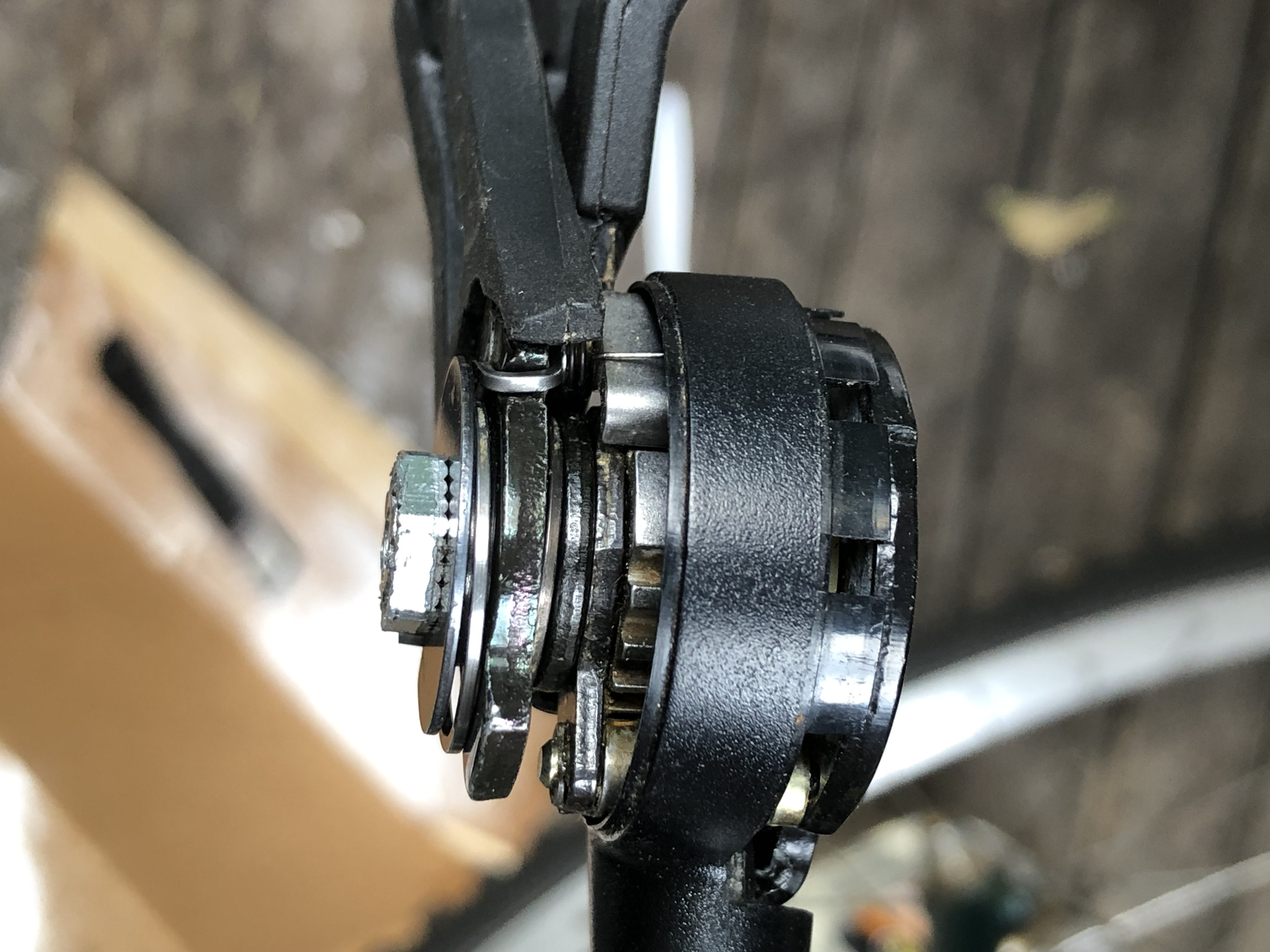
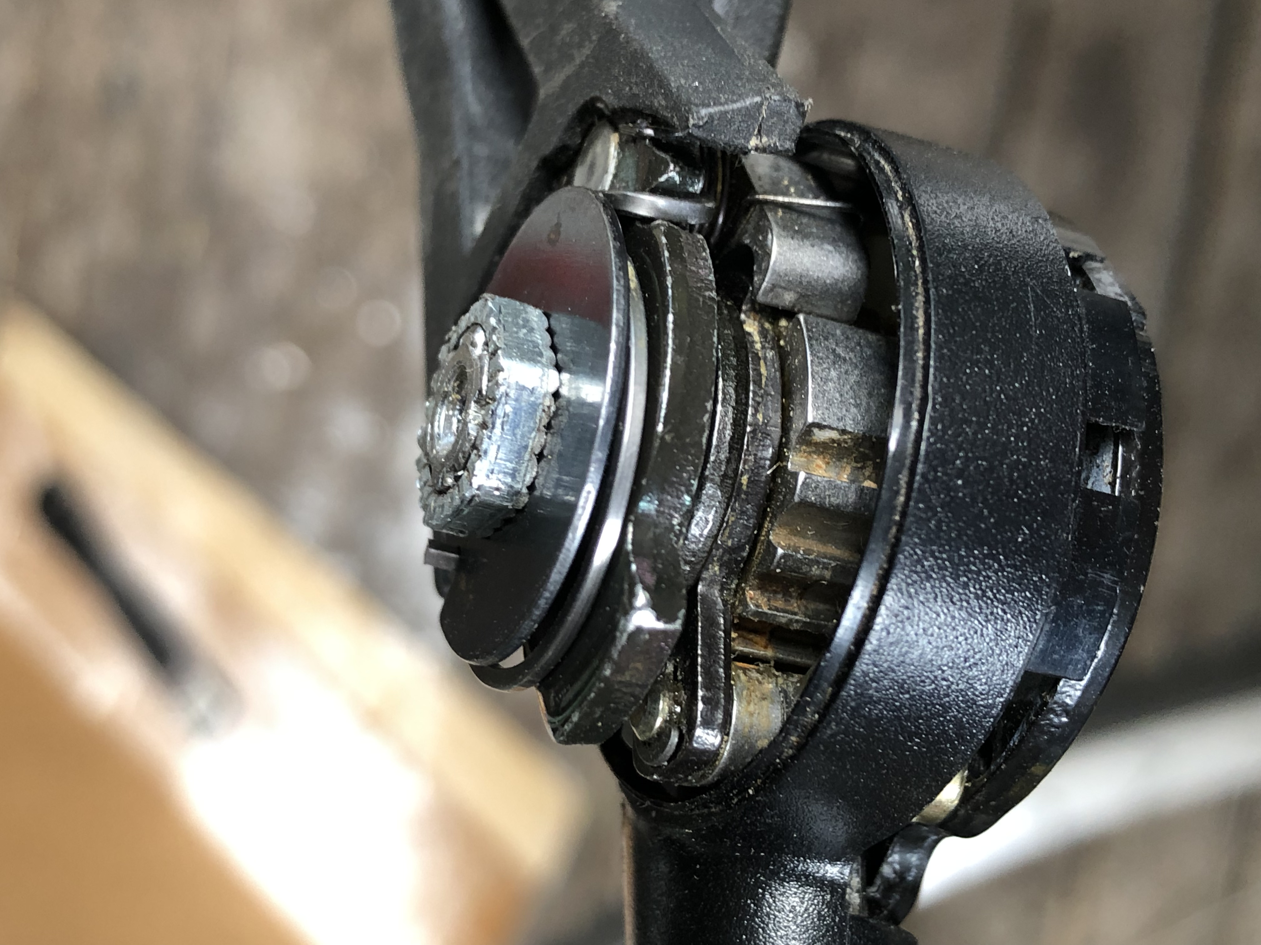
Take apart the mechanism per any one of the many YouTube videos (or have a look at the photos here from the bottom up). Then place all the parts in degreaser and clean them all up.
I recommend that you scroll to the bottom of this page and look at the photos going up which will show you the disassembly. NOTE THAT THE FIRST NUT YOU HIT IS REVERSE THREADED - Clockwise to loosen, anti-clockwise to tighten.
Click on any of the images to enlarge.
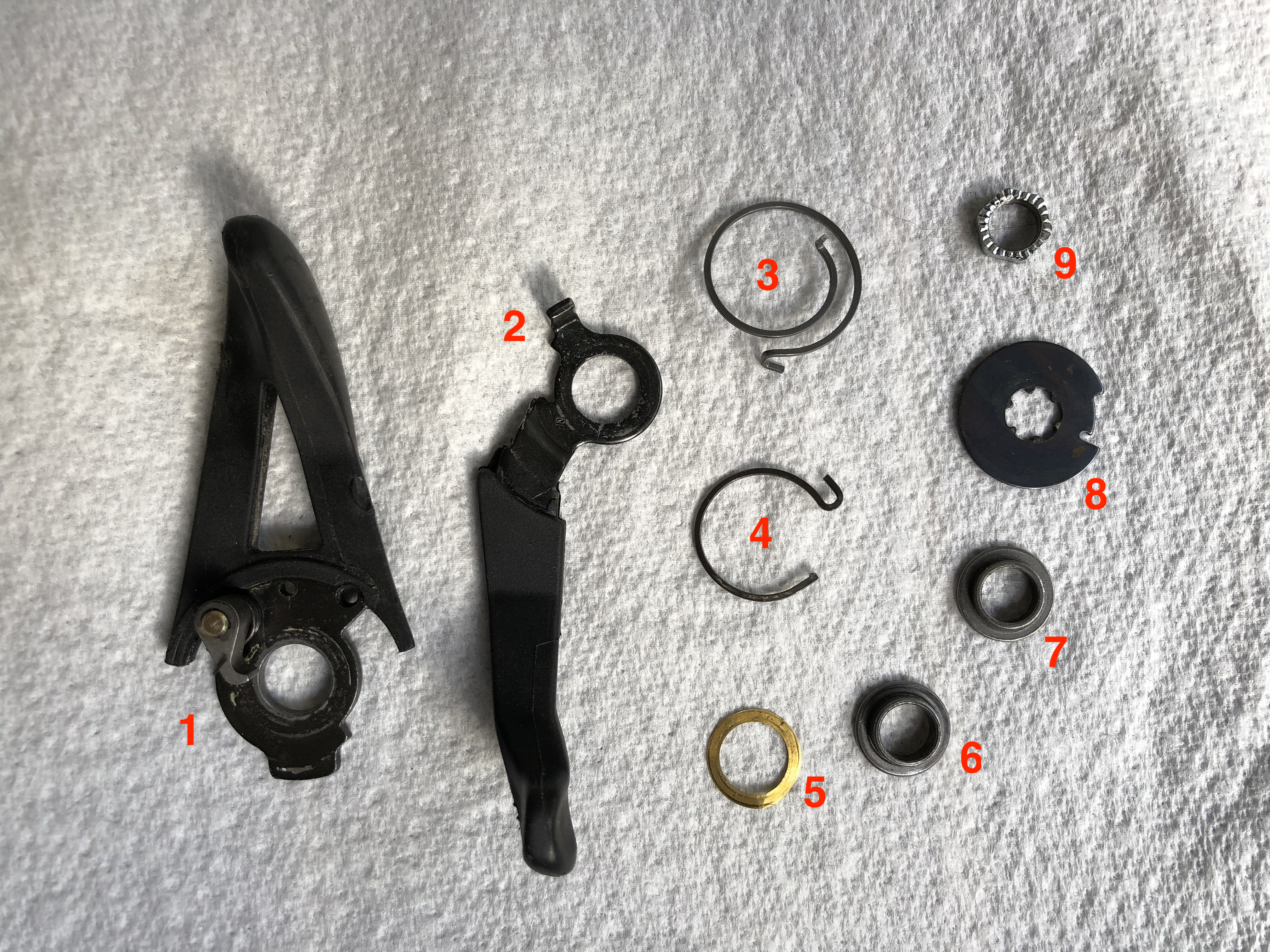
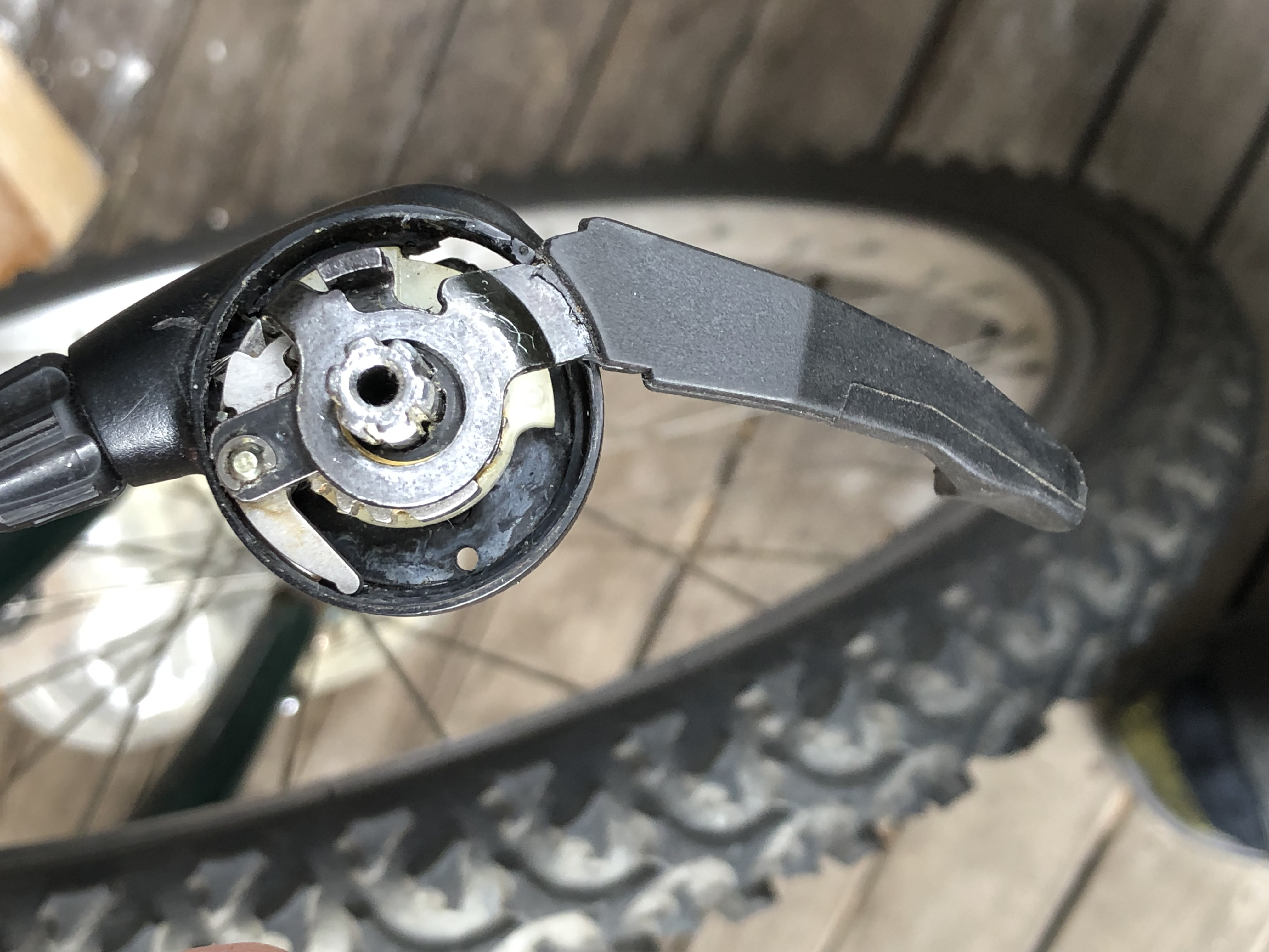
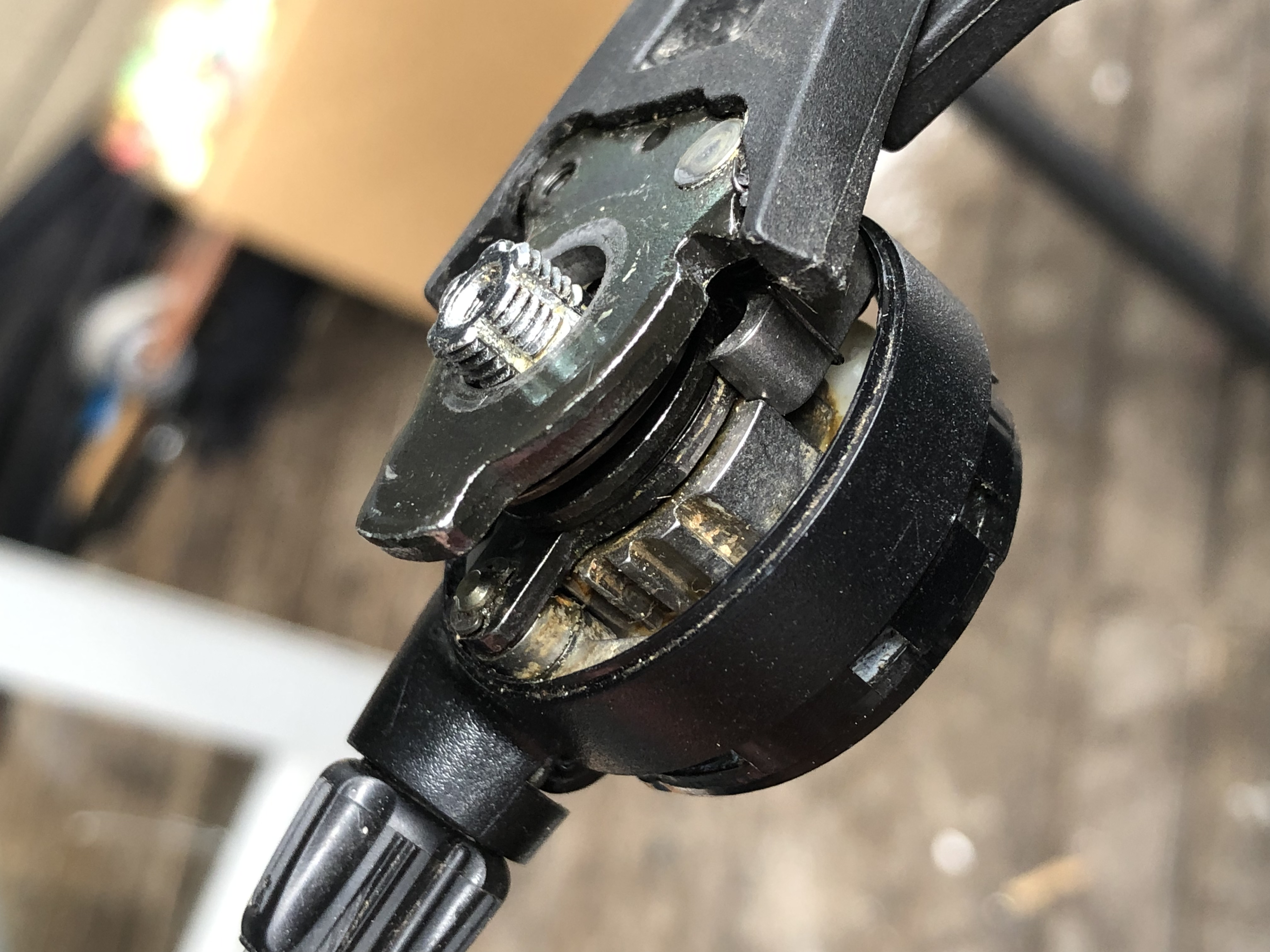
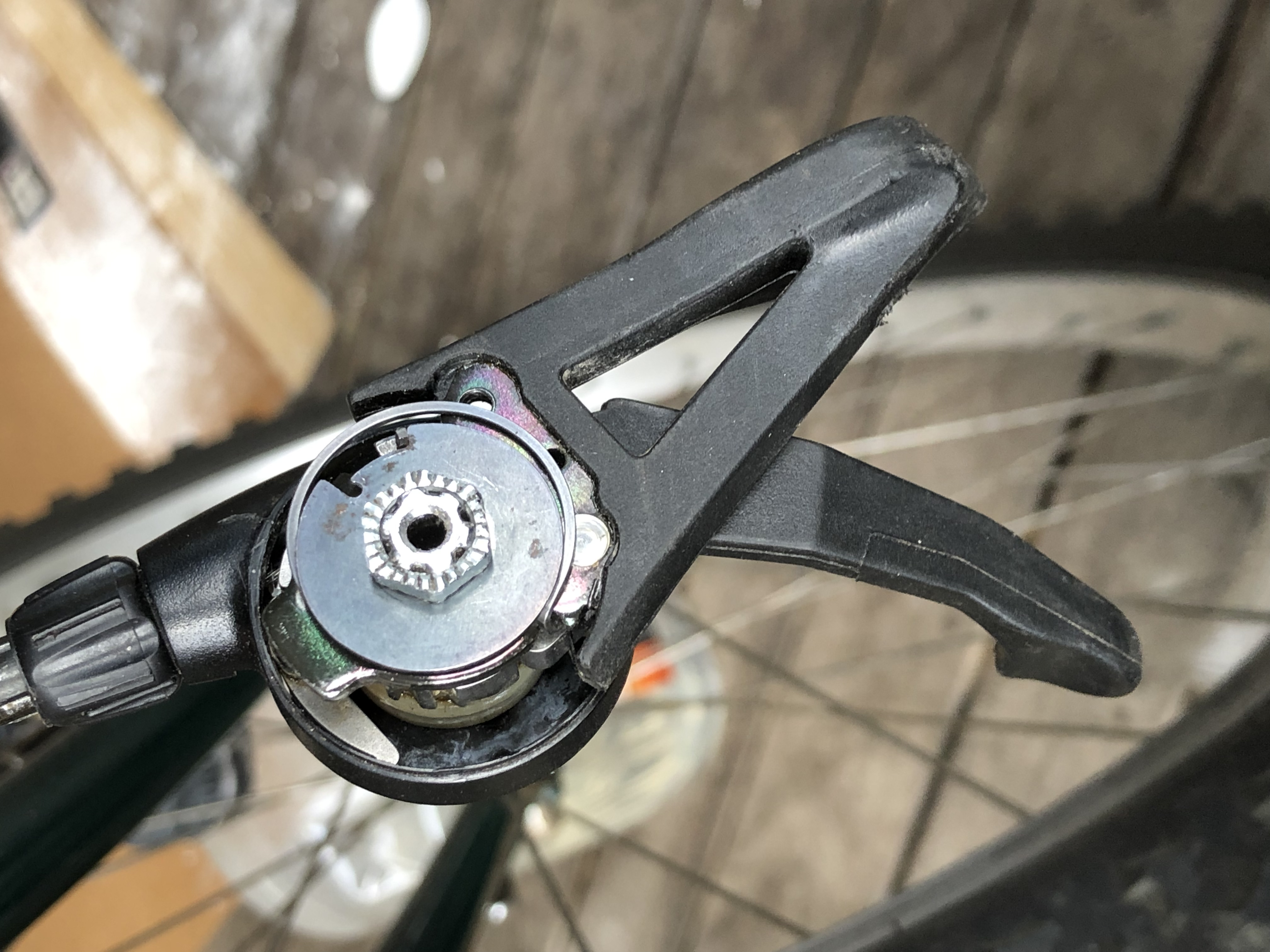
The larger lever (#1) has a little spring loaded mechanism which is what gets stuck and prevents the shifter from working. It needs to move freely and return quickly when you press against the spring. I was able to achieve this by soaking the whole part in degreaser, but you may need to remove the circlip and fully tear apart if that doesn't do the trick.
Also note the following:
The copper bushing (#5) is very thin and easily bends.
The silver bushings marked #6 and #7 are not identical, but look very similar. They are sized to correspond to the two levers (marked #1 and #2).
The springs (#3 and #4) are best removed and installed carefully with needle nosed pliers and make sure they don't fly off somewhere never to be found again.
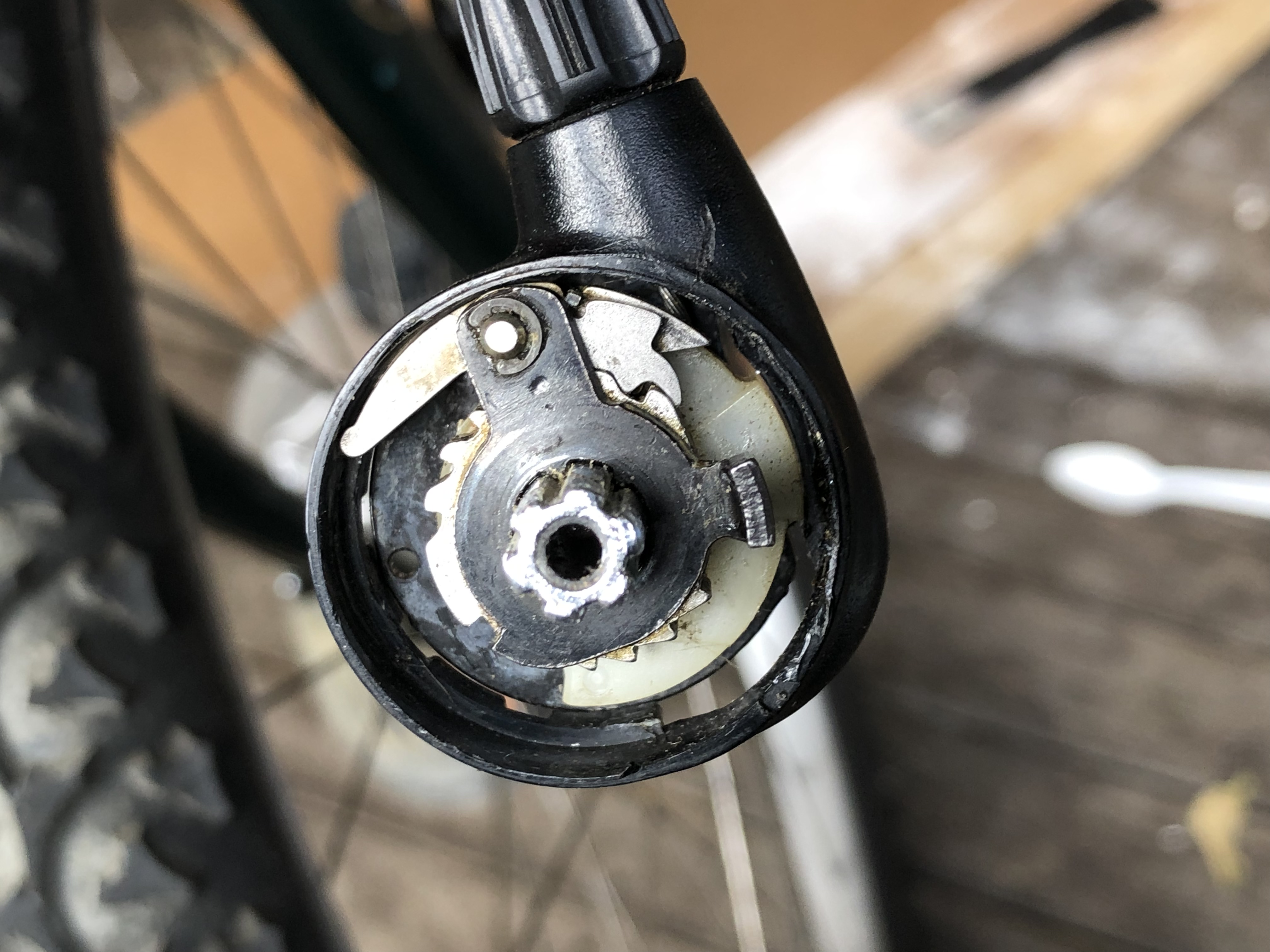
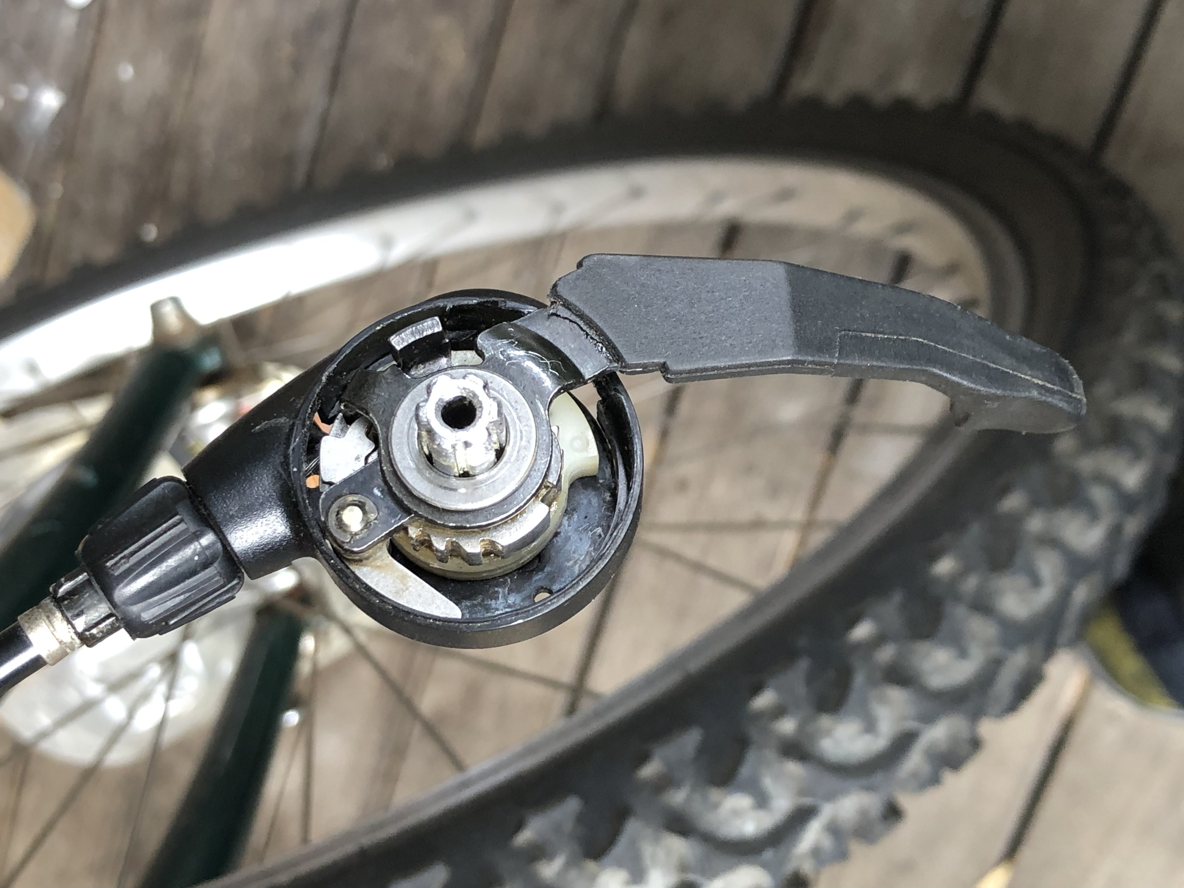
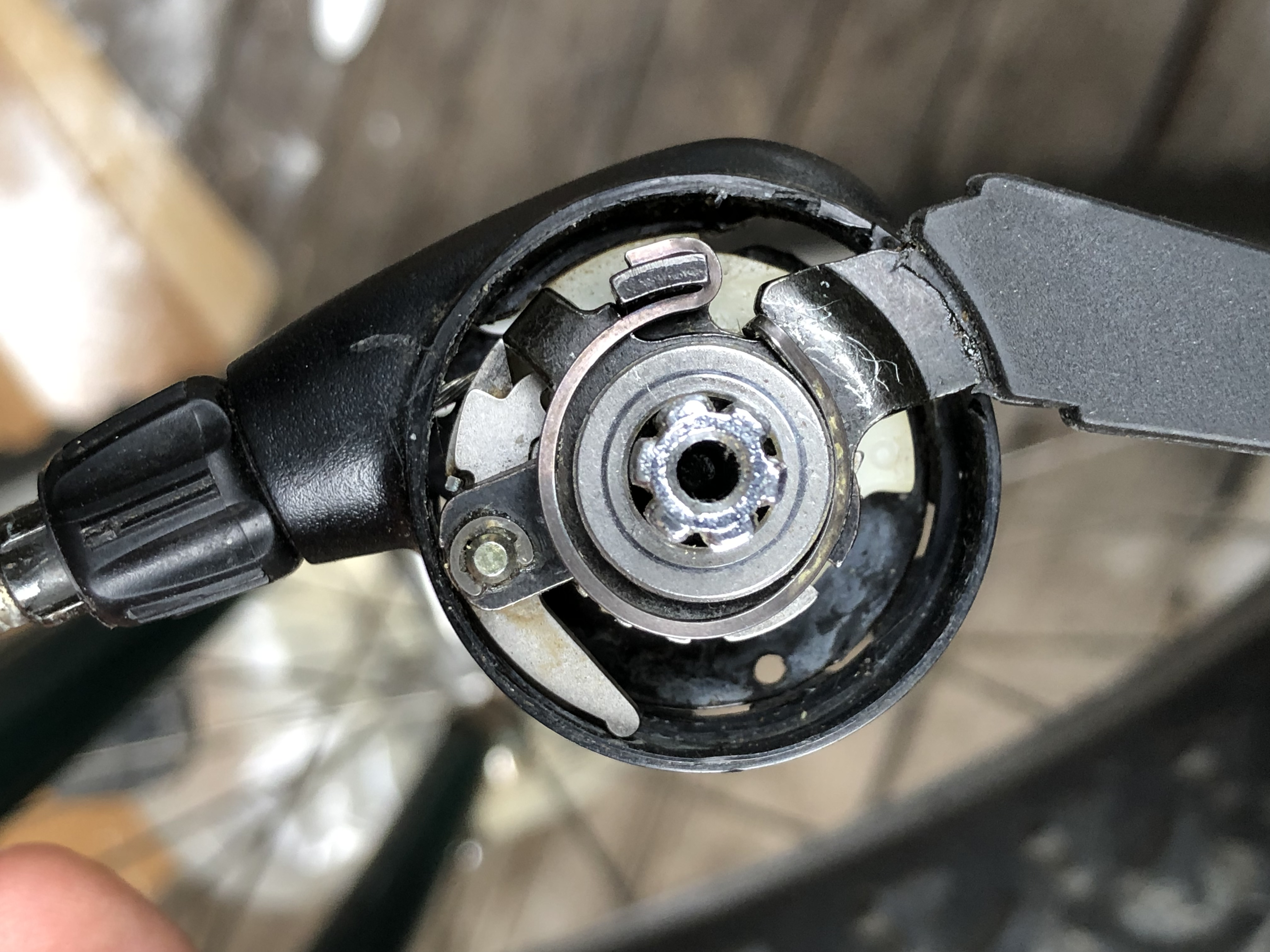
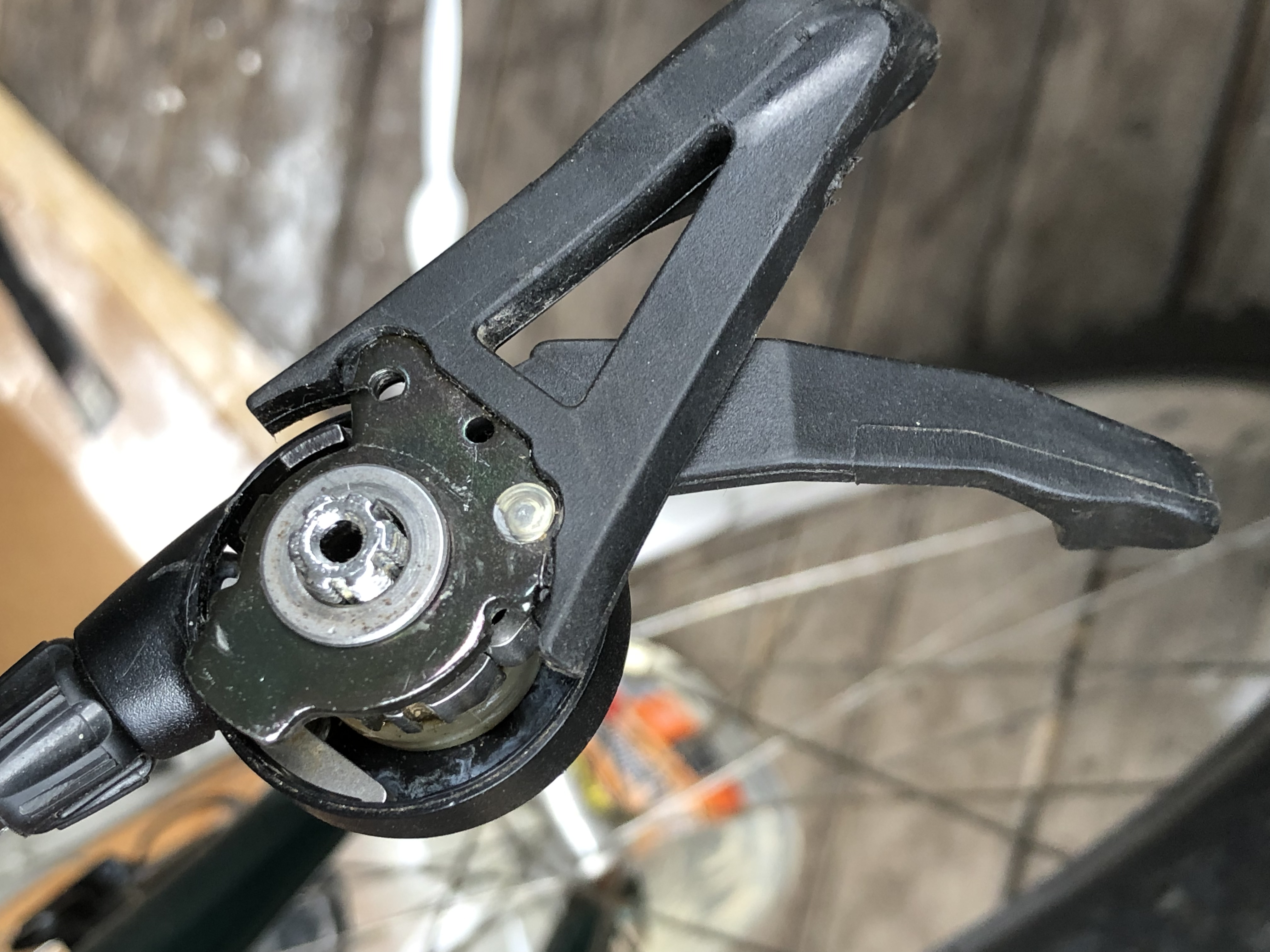
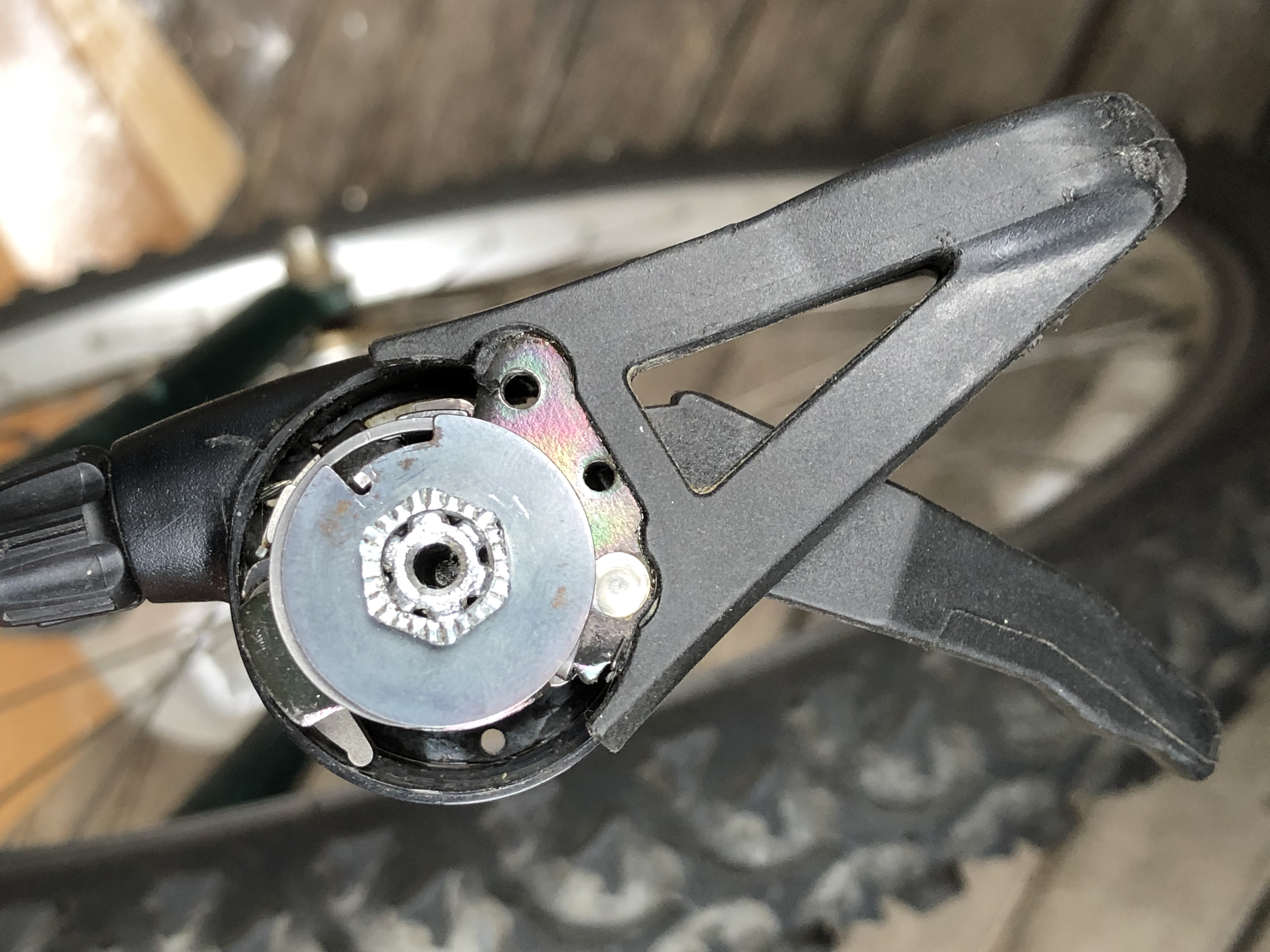
With all the parts removed, the mechanism looks like the figure above. I was able to clean this just by soaking it in degreaser and I didn't need to remove the cable itself.
To put it all back together you start with making a "sandwich" with #2, #5 and #7 from the top image. I
found it easier to put the copper part in first and then the other two,
but keep in mind that you don't want to damage the thin copper bushing
(nor lose any of the items). You can see I slightly bent the copper bushing already here.
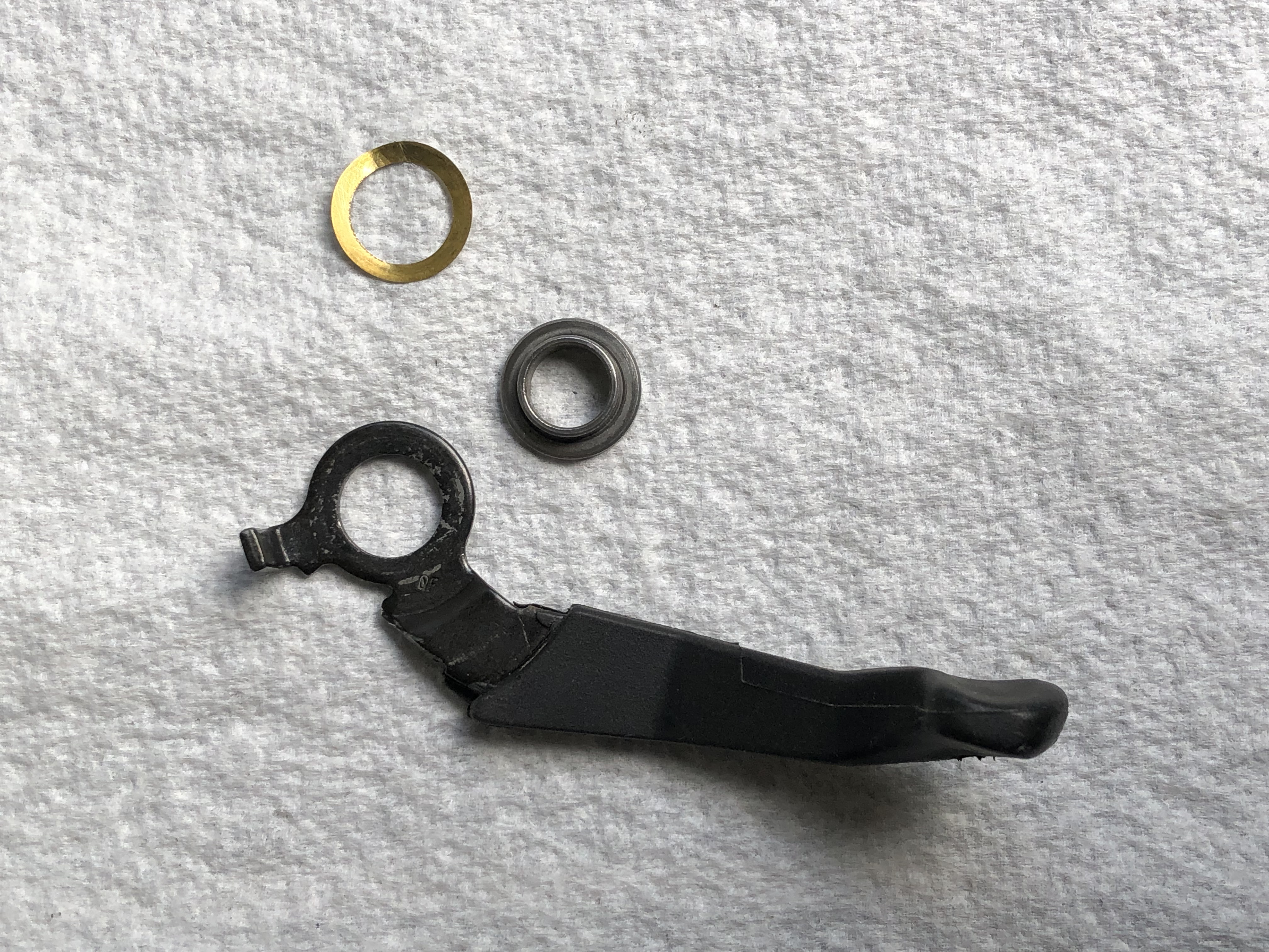
I put the copper bushing in first...
Then the silver coloured bushing labelled #7 goes next with the flat part on the top and the cylindrical part on the bottom. This is used to centre the lever correctly. Make sure that you don't damage the copper bushing below.
And there you can see how the lever becomes nicely centered on the shaft. Next is the spring - you will need pliers to fix it on one end and bend it around to the other end. It needs to be under stress for it to work.
Then comes the next lever and I have two photos to show exactly how it goes below.
Then you will use the bushing marked #6 to center it like you did with the other lever.
Next is the spring which can be a bit confusing. One end will latch onto the lever, the other end will be sticking up waiting for the next piece of the sandwich.
Then you align part #8 so it can fit down the shaft and it should be aligned to catch the part of the spring that is sticking up in the groove.
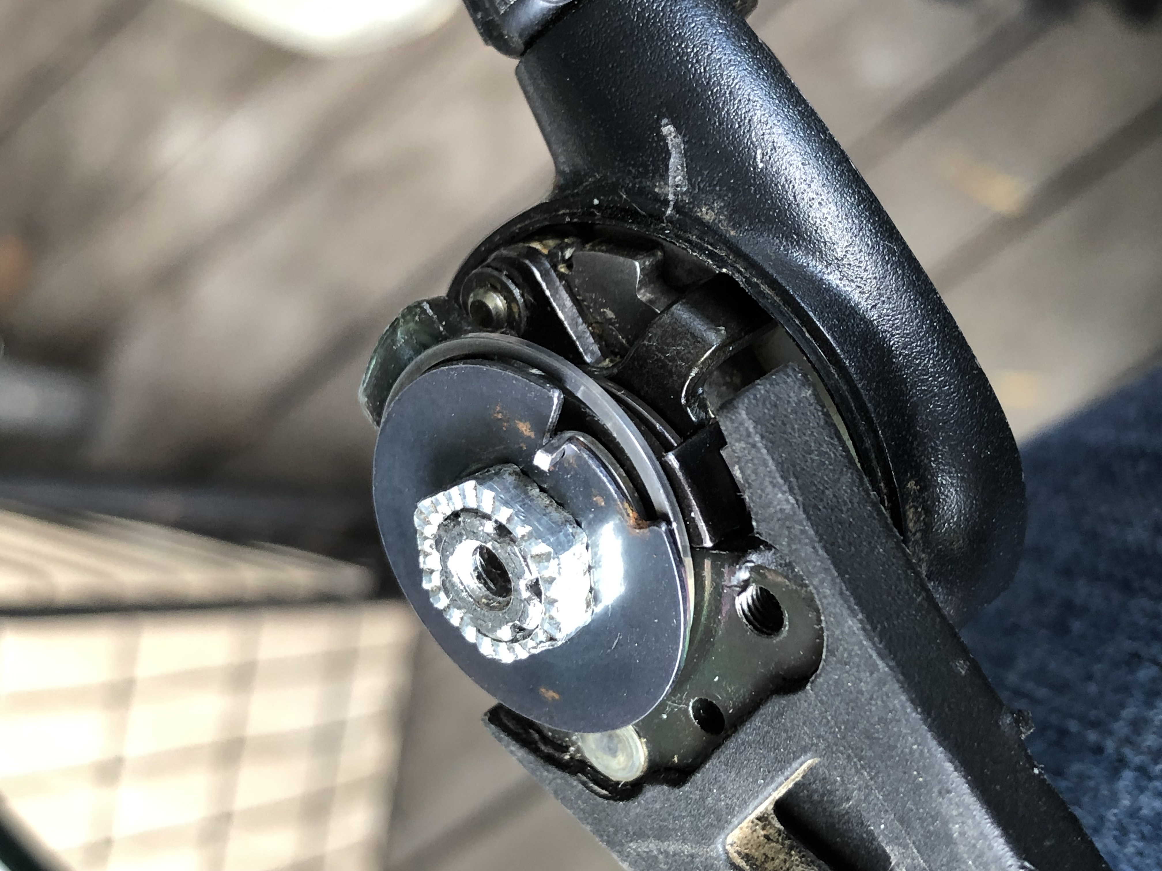
Then you tighten on the last piece of the sandwich (marked #9 in the top image). KEEP IN MIND THAT THIS IS REVERSE THREADED! You turn clockwise to loosen and anti-clockwise to tighten.
Then there is one more step which is to use pliers to pull the spring into the deeper grove as per the photo below.
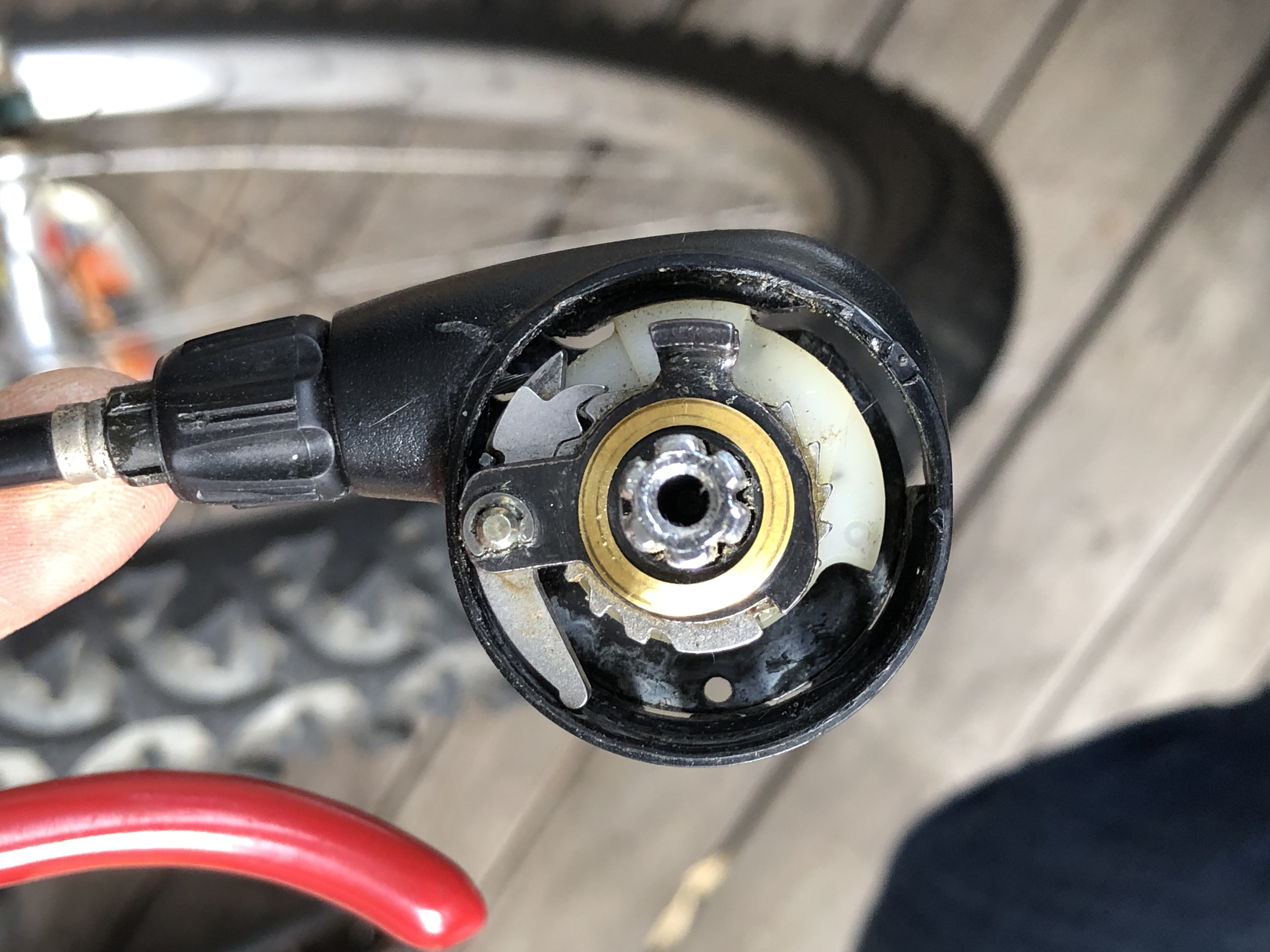
And here are some photos of the finished assembly from different angles.
This is exactly what I needed to rebuild my 7 speed Altus A-20...you are a god send my friend! Thanks for the step by step pictures!
ReplyDeleteMy lever suddenly fell down last week. Bought in 1994, repair needed 2022 - coincidence? ;-) Thanks to you the repair was easy. So thank you for your detailed instructions!
ReplyDeleteYour blog saved me! I took the shifter apart and couldn't put it back together. No YouTube videos explained how. THANK YOU!!!!
ReplyDeleteThere's one step missing, and that's inserting the outside plastic ring between the two levers.
Irmão tu salvou meu dia, aconteceu exatamente comigo como foi contigo, parou de funcionar aqui a alavanca 7v , desmontei sem tirar fotos e me ferrei, aí pesquisando aqui nada de vídeo explicando, aí encontrei seu post , muito obrigado ✌🏾
ReplyDeleteThank you very much, it was perfect for me to assemble the shifting mechanism, since I hadn't taken any photos.
ReplyDeleteThank you very much, it was perfect for me to assemble the shifting mechanism, since I hadn't taken any photos.
ReplyDeleteThank you for this. I had the no-shift issue on a 1993 bike that hasn't been used in 20 years. I wasn't looking forward to the hassle of replacing the shifter. Your clear and complete instructions with hi-res photos were invaluable in fixing the old one in situ.
ReplyDelete